10-2-1 Wiring Electric Brakes

10-2-1 Wiring Electric Brakes

If your vehicle is not equipped with a plug-and-play harness you can also splice in wiring for connecting a brake controller. Works with most 3500 lbs trailer axles in the market.


Amazon Com 10 X 2 25 Trailer Electric Brake 1 Right 1 Left In Pair Automotive

4 mounting bolts installed no nuts included.

10-2-1 wiring electric brakes. The RED stoplight wire must be connected to the cold side of the brake pedal stoplight switch. Connect the two wires from the clutch or pins 2 6 are connected internally. During forward travel the brakes automatically adjust to deliver optimum performance and braking power.

In most cases problems with electric trailer brakes occur either because of corrosion in the trailer connector or a break on the wiring between the connector and the brakes themselves. Tail License 3 Tail License. DEXTER Forward Self-Adjusting 10 x 2-14 Right Hand complete electric brake assemblyThe design of Nev-R-Adjust brakes utilizes an innovative forward self-adjusting feature.

I have attached an electric brake installation video for you to check out. The temperature rating on the coating is 221 degrees Fahrenheit. In Step 2 there are instructions for drilling through the firewall.

We then run a jumper wire from the electric brake power wire to the right side brake assemblies see photo. G G Electric Plumbing at 1900 NE 78th Street Ste. Brake cable is used for many automotive truck and trailer applications Flat jacketed PVC insulation Tough gray over plastic insulated wires Resistant to oil grease acids and gasoline Available with 2 3 and 4 conductors 246 x 432 625mm x 1097mm nominal OD.

Electric Brake 2 Electric Brake. Red 14 Gauge. The wire in the Jacketed 2 Wire 10 Gauge Brake Wire item 10-2-1 is stranded and designed for automotive applications.

If you want to use duplex wire you can use part 10-2-1. Home Dexter Axle Hardware Dexter Brake Assemblies Dexter Electric Brakes Dexter 10 Electric Brakes Complete 6450612 10 x 225 Electric 4400 Nev. Pair of 10 x 225 Genuine Dexter Part K23-026-00 K23-027-00 electric trailer brake assemblies with parts.

Premium LIBRA brand OE 10 x 2-14 electric trailer brake assemblies 1 left 1 right for one axle. Brake cable is constructed in two conductor configurations for 18 gauge 16 gauge 14 gauge 12 gauge and 10 gauge wire. C Make sure to tighten down fuse screws.

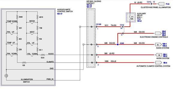
2 INSTALLATION 222 Wiring Diagrams To 24V Vehicle Brake Light trigger refer to section 221 To 12V Trailer Blue Brakes Red 25A Fuse or 30A Circuit Breaker CBK30-EB 24V Vehicle Start Battery Ground White Black-Dash mount controls for Tow-pro. Exchange with Dexter brake 023-026-00023-027-00. Common Ground 1 Common Ground.

Yellow 14 Gauge. This means that a double axle brake system would be drawing a maximum of 16 amps for a full emergency stop. The brakes are manual adjusting with access points on the backs to turn the adjuster.

Green 14 Gauge. DO NOT disturb the position of the switch. Brown 14 Gauge.

TruRyde 10 x 2-14 Electric Brake Assy. How many amps does a brake controller draw. Once the backing plate is attached to the weld rings the drum is then fitted and tightened with the axle nut.

Your factory tow package if you have one might already have this wire running from under the dash to the battery with some kind of circuit protection. - Right Hand 35k 112101. This is the wire we use to wire the brake output wire and the 12 volt power wire when.

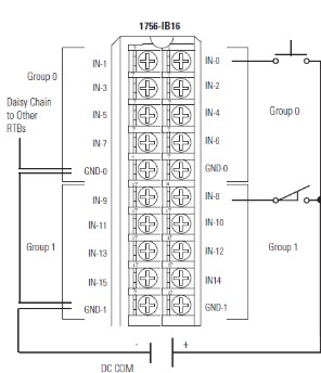
3 4 holes mounting bolt circle diameter. Connect the switch provided by the customer between terminals 7 8 and 3 as shown in the Connection diagram. 1-4 Wire the first 4 pins just like above and the 5th line goes to the brakes.

Blue 12 Gauge. 1-2 axles 30 amp for 3-4 axles to the POSITIVE terminal of the battery. This allows for use of the wire for up to 40 amps at up to 25 feet.

Black 10 Gauge. White 10 Gauge. Blue Electric Brakes or Hydraulic Reverse Disable See Blue Wire Notes below 6.

Red or Black 12V Auxiliary Power See Red Wire Notes below 7. Weve found the most common amperage draw on a 7-inch brake magnet to be 32 amps maximum. Connect the AC input to terminals 1 and 5.

The BLACK wire is the power supply line to the brake control. The F1009 by TruRyde manufacturer part numbers BK-10E-01 and BK-10E-02 is an economic choice for 10 electric brakes. The most common electrical problem is low or no voltage and amperage at the brakes.

CURT 51437 Quick Plug Electric Trailer Brake Controller Wiring Harness Select Ford F150 F250 F350 F450 F550 Super Duty Lincoln MKT Navigator black 46 out of 5 stars 118 1125 11. To relay Fuse screws To switched power source. The increased amperage of a 10 or 12-inch brake magnet tends to max out at 4 amps.

24V INPUT 125mm² 125mm² 30mm² 30mm² The Input Power Black wire should be. Black and white with gray outer jacket. This brake is rated to a maximum capacity of 3500 lbs.

B The circuit used for connection must have an 8 to 10 amp fuse. To brake booster 5 Next wire the fuse to a positive ignition switched power source. Center Auxiliary 7 Center Auxiliary.

Sizes 12 and 10 gauge are recommended for electric brake wire. Mounts to 4-hole axle brake flange. Splice down line from the switch.

101 Vancouver Washington 98665 HOW TO CALCULATE WIRE AND FUSE SIZES FOR ELECTRIC MOTORS Because electric motors have a tremendous amperage draw during the starting phase wire and fuse sizes must be calculated very carefully. 10-inch Electric brakes are suitable for any axle up to 50mm in diameter. Common causes of this condition are.

Electric trailer brake systems utilize a magnet to spread the brake shoes against the brake drum which slows the trailer down. 10 x 2-14 Right Hand complete electric brake assembly. This kit comes comes with the left hand and right hand brakes plus the hardware to mount on a 3500 lbs.

Right Stop Turn 6 Right Stop Turn. If not a wire must be run through the firewall and connected directly to the battery with an in line circuit breaker. I recommend using 12-gauge wire 12-1-1 for the jumper wire and for additional ground wire.

Battery Charge 4 Battery Charge. Connect the two wires from the brake or clutch to terminals 2 and 8 of the socket. A Positive connection must be a switched source or pump will run with key off.

The BLUE brake output wire must be connected to the trailer. Poor electrical connections open circuits insufficient wire size broken wires blown fuses fusing of brakes is not recommended improperly functioning controllers or resistors. 10-inch Electric braking systems use a four-hole weld ring to secure the 10-inch electric-backing plate to the axle.

For Alko Dexter Quality or other popular trailer axle manufacturers. Left Stop Turn 5 Stop Turn. In this guide we cover step-by-step how to install a brake controller.

Only works on 3500 lbs trailer axles with four hole brake flange. Be the first to review this product. Even during the run cycle of a motor if the voltage is low it will.

Installing a brake controller involves disconnecting the vehicle battery mounting the brake controller onto dash and plugging the unit in with a vehicle-specific wiring harness.

04 F150 Radio Wiring Diagram

04 F150 Radio Wiring Diagram

Ford 1996 F-150 F-250 F-350 F-Super Duty and Bronco stereo wiring. Thanks for any help.


Solved I Need A Wiring Diagram For The Steering Wheel Fixya

You can also opt to use a wiring loom but in the event your F150 wires are hacked up and you need to know what the speaker wires are here they are below.

04 f150 radio wiring diagram. The BCM body control module is located on the. Ford Mustang mach 460 1994 stereo wiring connector. Wire diagram 04 ford f150 2004 ford f150 wiring diagram wiring diagram radio 2004 ford need wiring.

1974 f100 f350 8 pages complete 3259 x. Power Door Lock Negative Wire Location. The F-150 uses a single wire to send commands to the factory radio so you can install either adapter without much trouble.

2004 Ford F150 Truck Car Alarm Wire Diagram. Light BlueRed Car Stereo Antenna Trigger Wire. Here is a complete list if what goes where.

These instructions will be easy to comprehend and implement. Find the Ford radio wiring diagram you need to install your car stereo and. Posted by Anonymous on Jun 25 2011.

1999 ford f150 radio wiring diagram. 2004 ford f 250 wiring harness diagram auto electrical wiring. Here is the stereo radio wiring information for your 2004 Ford F-150 F150 body with the standard or amplified systems.

Ford car radio stereo audio wiring diagram autoradio connector 2011 f150 faint 4balmoond mooiravenstein nl ac7b 2004 grand am resources 2bef 04 f 150 harness crown victoria database f250 super duty trailer online 1997 explorer taurus lair balmoond16. 1998 f150 lariat cassette player radio with a remote 6 disc changer cant find it any where your database below only has base models I think. 2004 Ford F150 Radio Wiring Harness Diagram.

2004 ford f250 radio wiring diagram. I need to know what wire is what in the 2 connectors on the back of the radio. Diagrams for the following systems are includ.

2004 F150 crew cab radio wiring. Car radio wire diagram stereo wiring diagram gm radio wiring diagram. 99 F150 Wiring DiagramIt shows the components of the circuit as simplified shapes and the power and signal contacts in the company of the devices.

Car Radio Illumination Wire. In Drivers Door Boot or at BCM Green Plug Pin 9. 1998 Ford F150 Stereo.

A single trick that I actually 2 to print out exactly the same wiring plan off twice. Craig ask and you shall receive. 2004 - 2008 Ford F150 - Radio wiring diagram - I have a 2004 F150 and Im looking for a wiring diagram for the radio.

Save your money the chip is a ohm resistor at Radio Shack for under 200. 2004 ford f150 radio wiring diagrams has been viewed 3070 times which last viewed at 2020-06-09 214724 and has been downloaded 4 times which last downloaded at 2016-03-22 093912 uploaded by Grace on 23 Mei 2014. Ford F150 stereo wiring connector.

All of the diagrams Ive seen - Answered by a verified Ford Mechanic We use cookies to give you the best possible experience on our website. 2004 ford f250 radio wiring diagram 1998 ford F150 Stereo Wiring Diagram Awesome ford F350 Trailer Wiring Diagram with 70f350 Master In. When you employ your finger or perhaps the actual circuit along with your eyes it may be easy to mistrace the circuit.

Problem with this system is that you can not adjust anything. Does anyone know the color codes for the. - Does anyone know which color wires are the rear speakers at the stock headunit.

2004 - 2008 F150 - 2004 f150 audio connector PINOUT and wire color information for single cd system - I went ahead and did the dirty work yesterday of metereing and testing everything to find which wires go to what because I could not find it on the web anywhere. 2007 ford f150 wiring diagram for power harness gm 94 brakes full 2005 pdf 2000 free vss f 150 supercrew reverse lights how to wire ac maforce focus trailer 92 points plug stereo 1984 4 7 blade 2006 daewoo edge kohler 2008 window tz 2577 1994 diagrams 97 1968 1993 ignition radio factory request 1990 brake light 1997. FORD Car radio wiring diagrams.

It will be useful when installing an aftermarket radio sound stereo system or other automotive accessories. Looking for stereo wiring diagram and plug pinout for 2004 F150 XLT 6-disc 4-speaker. This video demonstrates the Ford F150 Complete Wiring Diagrams and details of the wiring harness or connectors.

At Headlight Switch Or BCM Blue Plug Pin 6. 6x8 speakers drop right in most 5x7s will also fit and 5-14 speakers will fit in with mounting brackets. May 28 2019 at 804 pm.

I need a wiring diagram for the steering wheel radio controls and horn for a 2004 Ford f150 4x4. 2004 F150 Speaker Wiring Diagram. Using a stereo install kit is easy to do to mount your motorized or double DIN stereo into this F150 truck.

Parking Light Positive Wire Location. Print the wiring diagram off plus use highlighters to be able to trace the routine. 1999 ford F150 Stereo Wiring Diagram wiring diagram is a simplified agreeable pictorial representation of an electrical circuit.

Replacing your factory speakers This truck will accept several speaker sizes. Need to find IATMAF sensor diagram for 2003 Ford Ranger. This circuit and wiring diagram.

Installing chip and want to double check wiring. 2004 ford ranger radio wiring diagram 1999 f250 diesel wiring-diagram 2004 ford e350 radio wiring diagram 1999 f250 wiring schematic 1979 ford f-250 starter wiring 2003 f250 radio wiring diagram 89 ford f-250 wiring diagrams 04 f250 headlight. 1995 Ford F150 Radio Wiring Diagram Example Of 2001 Ford F250 Radio Ford F150 Radio Wiring Harness Diagram.

Its a 6 CD AMFM with 6 speaker unit. 1997 - 2003 Ford F150 - Need color code for radio wiring - Im trying to replace factory amfm cassette stereo in 1999 f-150 with aftermarket cd player and the wiring harness doesnt match up. RADIO Base Radio Premium Sound Radio Wiring Diagram RADIO Ford Pickup F150 1998 SYSTEM WIRING DIAGRAMS.

PORTAL-DIAGNOSTOV LoginSign up email protected INN 780629886224 Currency. Id like to add an amp and bass tube but I need to install a convertor for the rca jacks. It splices in to you IAT wire harness located at the intake tube between the air filter housing and throttle body.

Here is the stereo radio wiring information for your 2004 Ford F-150 F150 body with the standard or amplified systems. Wiring Diagram will come with a number of easy to follow Wiring Diagram Instructions. Its intended to aid all of the typical consumer in creating a proper method.

The BCM body control module is located on the drivers side rear cab wall.

1966 Chevrolet Truck Wiring Diagram

1966 Chevrolet Truck Wiring Diagram

1987 Chevy Truck Ignition Switch Location. With this sort of an illustrative manual you will be capable of troubleshoot stop and total your assignments.


1966 Chevy Pickup Dash Wiring Diagram The H A M B

Pin On Projects To Try.

1966 chevrolet truck wiring diagram. A detailed schematic of the wires on the 1966 Chevrolet. The two wires coming in to the regulator are for keyed power and the generator light. Very clean truck but the wiring is in bad shape.

1976 chevy truck steering column wiring diagram 0 Comment on 1976 Chevy Van Wiring Diagram Posted in Wiring 1976 Chevy Van Wiring Diagram Ryan July 15 2021 Search Search Recent Posts 87 Ford Ranger Radio. 1966 Chevy Truck V8 Two Wheel Drive Automatic. It shows the various electrical circuits fuses distributor etc.

Ive used them before and had excellent service. If youre tired of trying to read and decipher cryptic black and white wiring diagrams out of your old shop manual this wiring diagram is the solution. With points and dont have or cant find resister wire this may help.

Need of help on wiring diagram 1966 c10 chevy inline 6. I had trouble figuring out the wiring for the startrun circuit going to the points. Pin On Automovil.

1 trick that We 2 to printing a similar wiring plan off twice. They have copies of the original GM wiring diagrams for your truck for 8. 1968 through 1972 diagrams show standard indicator light and optional full gauges printed circuit board connectors.

1964 1966 Chevy Truck Installation Manual. Pin On Wiring. The connectors are shown with end-on views with Vacuum diagram for 78 chevy c10 pu 250 inline 6 1978 Chevrolet Truck.

1964 wiring diagrams - The 1947 - Present Chevrolet GMC Truck Message Board Network 1964 wiring diagrams The 1960 - 1966 Chevrolet GMC Pickups Message Board Joe Bruce. The wire is not on the diagram above. Oem Wiring Diagrams 1966 Chevy C10.

66 Chevy Truck Wiring Diagram. Gauge Wiring Diagram. 1966 CHEVROLET TRUCK Wiring Diagrams.

1966 chevy pickup dash wiring diagram 14515c chevrolet 60 66 full body the 1947 color classic oem diagrams c10 1964 colored hei and starter 67 72 harness complete 1960 gmc truck headlight trouble shooting underhood laminated install question 1980 1987 repair guide electrical help 63 turn signal on a ignition switch non. Need to know the color codes of every wire and where they need to hook up to on a 1967 chevy c10 pickup. 1966 CHEVROLET Truck Sales Data Book There is also a 1960 - 1966 Chevy Truck Factory Assembly manual.

Most of the original wiring was missing on my truck. They are laminated back to back in heavy plastic for durability no more. 64 Chevy C10 Wiring Diagram Chevy Truck Wiring Diagram 1963 Chevy Truck Chevy Trucks 1966 Chevy Truck.

All diagrams include the complete basic truck interior and exterior lights engine bay starter ignition and charging systems gauges under dash harness rear clip etc. Dixiedog Sep 26 2005. I need a wireing diagramcoupefirewallfuses.

1966 Chevy Truck wiring diagram. 1966 Chevy Truck V8 Two Wheel Drive Automatic. Pin On 64 Chevy Truck Ideas.

This manual has drawings and diagrams of many areas of the truck and show many details that can be handy when trying to restore or just fix things. 16 1984 Chevy Truck Headlight Wiring Diagram Truck Diagram Wiringg Net Chevy Trucks 1984 Chevy Truck Jeep Cherokee Headlights. Sbc Alternator Wiring Diagram In 2021 Alternator 68 Chevelle Chevy.

This diagram includes two 8-12 x 11 full-color drawings with the dash-to-engine compartment harness on one side and the dash to the rear lights on the other. 1963 all makes models parts 14512c chevrolet truck full wiring diagrams chevy c10 forums 60 66 body the 1947 present gmc message board network 63 turn signal on a 1 2 which wires go where wire colors are diffe 62 diagram corvette 179 receipts impala literature multimedia. Just acquired a 66 Chev C10.

If you are going to use the stock dist. 1966 chevy c10 wiring diagramCHEVROLET 1966 C10 PICKUP 53L 327cid V8 Literature Wiring Diagrams. 64 Chevy C10 Wiring Diagram Chevy Truck Wiring Diagram 1963 Chevy Truck Chevy Trucks 1966 Chevy Truck.

67 72 Chevy Wiring Diagram 72 Chevy Truck Chevy Trucks 67 72 Chevy Truck. Looks like a twelve year old got ahold of some duct tape and went to work. Electric 2 Speed Wiper Wire Diagram 1966 Chevy Truck Classic Chevy Trucks Chevy.

Sep 1 2014 - 1964 wiring diagrams The 1960 - 1966 Chevrolet GMC Pickups Message Board. March 26 2020 Page 2. Electric 2 Speed Wiper Motor Diagram 1966 Chevy Truck Chevrolet Classic Chevy Trucks.

I need a wireing diagram for a 1966 chevrolet nova 2 door coupe for the wires that come threw the firewall that link up to the fuses. It had been sitting in a field for 30 years or so. 1966 Wiring Diagram Chevrolet Pickup Truck The store will not work correctly in the case when cookies are disabled.

Gauge Cluster Wiring. Electrical Diagrams Chevy Only Page 2 Trailer Wiring Diagram Chevy 1500 Chevy Trucks. Does not include 8 cylinder engine.

90533 Mon Apr 15 2002 0612 AM. Headlight Switch Wiring Diagram Chevy Trucks Ford Trucks Light Switch Wiring. Copy Link to Clipboard.

When you make use of your finger or perhaps the actual circuit with your eyes it is easy to mistrace the circuit. Headlight Switch Wiring Diagram Chevy Trucks Ford Trucks Light Switch Wiring. Chevy Trucks 1963 Chevy Truck Chevy.

Generally speaking there are two wires that go out of the voltage regulator to the alternator. 64 Chevy Color Wiring Diagram The 1947 Present Chevrolet Gmc Truck Message Board Network Chevy Trucks 1963 Chevy Truck Chevy. 1979 1980 1981.

I ended up using the diagram that came with my harness EZ Wire from the Autometer guages - but I dont know what I am doing since when I dim the lights the guages move. Vocational Technical or Trade Scho. 64 Chevy C10 Wiring Diagram Chevy Truck Wiring Diagram 1963 Chevy Truck Chevy Trucks 1966 Chevy Truck.

Headlight Switch Wiring Diagram Chevy Trucks Ford Trucks Light Switch Wiring. Description These diagrams cover body and engine wiring configurations. It also includes electric windows seats wipers etc.

1970 Vw Bug Wiring Diagram

1970 Vw Bug Wiring Diagram

1970 Vw Beetle Voltage Regulator Wiring Diagram. VW 1500 Sedan and Convertible Wiring Key.


1970 Vw Beetle Wiring Diagram Vw Super Beetle Electrical Wiring Diagram Electrical Diagram

VW Buses from 1949 to 1967 including pictures descriptions and technical information of microbuses kombis panels standards pickups and more.

1970 vw bug wiring diagram. Fuel Injection Wiring diagram PDF 1963. Are you looking to restore a 1970 VW Bug. 1 - 8-amp white.

We hope this article can help in finding the. Next diagrams is fairly simple but making use of it in the range of how the system operates is the different matter. 1967 Bus Wiring diagram USA 1968-69 Bus Wiring diagram.

Steering column bearing with horn ring. 1966 Bus Wiring diagram USA 1967 Bus Wiring diagram. Access our free Wiring Diagrams Repair Guide for Volkswagen Air-Cooled 1970-1981 through AutoZone Rewards.

Dual Circuit Brake Switches and Warning Light Diagram. DIN Terminal Designations - a table of what those numbers on electrical parts mean. Lane Russell has received quite a few emails asking for the correct wiring diagram for the one year only 67 Beetle.

Thesamba type 1 wiring diagrams type 1 wiring diagrams for. Vw Generator Alternator Wiring Guide. Repairing the wiring on your air-cooled Volkswagen can be one of the most complicated and challenging parts of the restoration process.

It is likely that your VWs wiring has been tampered with by different owners over the years. Lost diagram of coil wiring on 74 type 1 VW bug. Key inside diagram Turn signals highlight Wiring Cheat Sheet 1973-75 1973.

Illustrated above is the VW 1500 sedan and convertible US. Vw Beetle Wiring Diagram 1970. Vw 1500 sedan and convertible wiring key.

Refer to a 1970 wiring diagram for more information on this and other updated circuits. 1971 Bus Wiring diagram. 1700cc Key inside diagram.

VW Tech Article 1970 Wiring Diagram. Horn except 1968 turn signals brake lights except 1969 and 1970 fuel gauge except 1967 Auto shift rear window. Diagram for 1970 vw beatle fusebox.

Here you can find some useful documents that might help you. Fanáticos De Los Volkswagens Volky Vw Beetle Voltage Regulator Wiring Diagram Facebook. Download the 1970 VW Beetle fuse box wiring diagram.

Buy this great How to restore a Volkswagen Beetle book. Vw beetle voltage regulator wiring generator alternator guide 69 bug issues in my 71 super thesamba com 1958 1967. Vw Tech Article 1970 Wiring.

1970 Vw Beetle Wiring Diagram wiring diagram is a simplified within acceptable limits pictorial representation of an electrical circuitIt shows the components of the circuit as simplified shapes and the talent and signal friends in the company of the devices. 70 rows Other wiring diagrams. Type 1 Wiring Diagrams intended for 1970 Vw Beetle Fuse Box image size 505 X 309 px and to view image details please click the image.

Stewart-Warner Southwind Gasoline Heaters. Vw tech article 1970 wiring diagram 1969 71 beetle thesamba com type 1 diagrams 1971 super 1968 69 convertible missing 1972 for 73. READ X13 Motor Wiring Diagram - Collection.

Diagram 1970 Bug Wiring Full Version Hd Quality Soadiagram Andreapendibene It. So anything could have become unwired. 1972 Bus Wiring diagram.

General Baja BugOff-Road vehicle wiring diagram. 1970 Bus Wiring diagram. Bus Fuse Box Wiring Wiring Diagram Dash Wiring Diagram For 1970 Chevy Impala Wiring Diagrams 1970 Vw Wiring Wiring Diagrams Volkswagen Voltage Regulator Wiring Diagram For 69 Vw Beetle 1970 Vw Ignition Switch Simple Guide About Wiring Diagram Vw.

Merged version Symbols sheet Alternator wiring Wiring Cheat Sheet 1973-75 1974-75. 1970 Vw Fuse Box Diagram. Our most sage advice is not only look from the diagram but understand how the constituents operate when inside use.

Vintage VW Wiring Diagrams. Fuses count 1 through 10 from left to right. The following is from here edited for 1967 through 1972.

Download the VW Beetle wiring diagram. Merged version Symbols sheet Alternator wiring Wiring Cheat Sheet 1973-75 1974-75. Vw tech article 1970 wiring diagram 1969 71 beetle thesamba com type 1 diagrams 1968 69 1971 super 1972 convertible missing help 1974 for 73 3 repair guide gallery volkswagen manual 1966 67 other alternator bus manuals pdf vwtyp1 1967 windshield wiper aircooled electrical hints vehicle apps android car group 2006.

Download the original owners manual for the 1970 Bug here. 1973-74 Bus Wiring diagram. If you havent overhauled your VWs wiring system it is likely the Volkswagens wires.

Also you will find excellent wiring diagrams for all makes years and models of VWs at VW Wiring Diagrams. 1966 Bus Wiring diagram. Vw bug wiring harness diagram thesamba com type 1 diagrams 1971 super beetle for 73 tech article 1970 1968 69 1974 75 need standard fuse panel volkswagen harnesses 1976 79 fuel injected 1955 57 aircooled the most useful 1973 1978 easy to read alternator 1972 sdy jim s home page vandetta kit car door regulator 1999 1954 1956.

Merged version Interior Lighting Fuel Injection Headlight washer Wiper Delay Front and rear fog light wiperdelay Wiring Cheat Sheet 1973-75 1976. Here is a picture gallery about 1970 vw beetle fuse box complete with the description of the image please find the image you need. 15 typically will connect black wire is used for on ignition live circuits such things as the coil and windscreen wipers will connect to this 31 31b nearly.

1970 vw beetle fuse box diagram 1970 vw bus fuse box diagrammeyer pump wiring diagram pot of gold wiring diagram wiring diagram for float switches 1984 ford f 150 wiring diagram harley davidson wiring for dummies kia sorento wiring diagram download archtop wiring diagramVolkswagen Beetle Ignition Wiring Diagram. 1970 vw beetle fuse box diagram 1970 vw bus fuse box diagrammeyer pump wiring diagram pot of gold wiring diagram wiring diagram for. This is a tutorial on how to put a custom steering wheel in a volkswagen beetle using a grant or momo adapter.

Vw Beetle Wiper Motor Wiring Diagram Source. Vw Tech Article 1966 67 Wiring Diagram. Images December 02 2019 Post a Comment.

Engine wiring schematic-1970-74 Type 1 and 1970-73 Type 3 with Air Flow Control models. 1970 Vw Beetle Turn Signal Switch Wiring Diagram Source. December 5 2020 1 Margaret Byrd.

1970 Vw Beetle Ignition Switch Wiring Diagram. Volkswagen air cooled 1970 1981 repair guide. Aug 4 2020 - 1970 Vw Fuse Box Diagram.

3 crucial steps on how to restore a 1970 VW Beetle. The person continued - The bug has had different stereos and other obvious work in the dash area. Removing a rusted steering column.

December 28 2020 1 Margaret Byrd. Version from August 1966 to July 1967 in all its glory. E Windshield Wiper Switch G Turn Signal and Headlight Dimmer Switch H1 Horn Button H2 Steering Column Connetion J1 Turn Signal and Emergency Flasher Relay J2.

Engine wiring schematic-1970-73 Type 3 without Air Flow Control and 1974 Type 4 with automatic transaxle.

1969 Gmc Truck Wiring Diagram

1969 Gmc Truck Wiring Diagram

Standard turn signal flasher hazard flasher and horn relay mounted on fuse panel. Free chevy truck wiring.


64 Chevy C10 Wiring Diagram Chevy Truck Wiring Diagram 1963 Chevy Truck Chevy Trucks 1966 Chevy Truck

Each kit includes all the basics needed to rewire a vehicle from headlight to tail light and will accommodate popular add-on items such as electronic fuel injection.

1969 gmc truck wiring diagram. Classic Update kits are designed for projects that require more circuits than would have been available in an original chassis harness. 14518 - 1969 GMC Truck Full Colored Wiring Diagram. Im not the creator of it but I can say that its accurate.

Most wiring diagrams provide detailed illustrations of electrical switches along with line drawing representations of wiring harnesses showing wire. 1969-72 Wiring harness will rewire truck from headlights to tail lights and is able to add many options and accessories. 1967-72 Chevy Truck Cab And Chassis Wiring Diagrams 68 Chevy C10 pertaining to 1965 Chevy C10 Pick Up Fuse Box by admin Through the thousand images online in relation to 1965 Chevy C10 Pick Up Fuse Box we picks the best choices together with greatest quality only for you all and now this photos is actually one among graphics selections in our greatest.

JEGS Wiring Diagram for 1969 GMC C K Series Truck 11 in. I rebuilt my entire harness by following this diagram. 78 Chevy Truck Wiper Motor Wiring Wiring Diagram All.

Some wiring system issues are more complex however. 1 trick that I actually use is to print the same wiring picture off twice. Click to view individual years.

1969 1972 Chevy Truck Forward Light Wiring Harness Warning Lights W Side Marker Other Vintage Car Parts Kennovation Services Auto And Vehicles. Receive free shipping brand new 24 98 guaranteed by mon apr 8 1969 gmc truck wiring diagrams manual pre owned 9 95 or best offer 2 98 shipping new listing 1969 69 ford f truck full color laminated wiring diagram 11 x 17 brand new 17 95 guaranteed by wed apr 10 buy it now 5 66 shipping need wireing diagram of one ton 1969 gmc truck posted by bill. X 17 in Laminated.

Select your Year Make and Model. Easy-to-follow illustrated installation manual included. Results 1 - 10 of 12 Find CHEVROLET L Ignition Coil Wiring Harnesses and get Free Shipping on Orders Over 99 at Summit Racing.

50 rows 1969-1970 Chevy Wiring Diagrams 100 Free to use or download and print. 1962 GMC Truck Color Wiring Diagram. Home TRUCK PARTS 1967-1972 Truck Parts Electrical Diagrams 1969 Wiring Diagram - Color.

11 X 17 18 X 24 Add to Cart Complete basic. 1988 90 gm r v series wiring schematic. Posted by kjfsnafu on Aug 04 2011.

Heres a wiring diagram I found from 67-72 Chevy truck forum. Back to FAQ Home. 1969 Chevy GMC Truck Wiring Diagram.

1971 chevy truck ignition wiring 72 switch diagram 67 1972 starter the 1947 1977 steering column gmc diagrams on c10 issues chevrolet dashboard switches and components full size cars 1968 1978 for 1970 80s trucks are wired ford 1967 plug w 69 wire color 70 c20 system circuit 1996 underhood technical drawings 1988 1999 catalog. 16 1972 chevy truck ignition. Chevy Truck Parts Chevrolet Truck Parts GMC Truck Parts Chevy Truck Part Classic Truck Parts Classic Chevy Truck Parts Chevrolet Truck Part.

Classic Update Kit - 1969-72 Chevy Truck. Ignition switch wiring the 1947 67 72 chevy diagram and under hood on 1972 c10 1967 gmc truck plug w underhood diagrams starter where does coil get it for stock dist to hei hot 70 c20 present chevrolet message 1970 80s trucks. 1969 - 1970 Chevy Wiring Diagrams.

When you make use of your finger or perhaps the actual circuit with your eyes it is easy to mistrace the circuit. Buy JEGS 19332 at JEGS. Shipping calculated at checkout.

1969 Gmc C3500 Ignition Coil Wiring Diagram. Need free wiring diagram for 69gmc truck 34 ton with a 307 engineKeep popping fuses and I lose my dash tail and brake lights dont know why. 1983 Chevrolet K1500.

1965 GMC C K Series Truck Color Wiring Diagram. All my videos are in 1080p so check that outjust an idea on how the GM HEI electronic distributor is wired up thanks for watching and please subscribe. Wiring diagrams are schematics of your trucks wiring and electrics systems.

67-72 Chevy Wiring Diagram. 1964 chevy c10 wiring diagram 1964 chevy truck ignition wiring for 1974 chevy truck wiring diagram image size 800 x 486 px image source. Chevrolet Cars Trucks.

Free chevy wiring diagram. Wiring diagrams description these diagrams use a new format. 1 trick that We 2 to printing a similar wiring plan off twice.

Therefore it will be necessary to modify the firewall of the 1961-1964 Chevy Fullsize cars the 1967-1968 Chevy and GMC trucks and the 1969-1972 Chevy and GMC trucks to accept the 1968 and later design bulkhead. Came to this site for the new model trucks but seen this and thought it. New floor dimmer switch is provided.

We are proud to have the ability to make vehicle specific free wiring diagrams available on request. Print the wiring diagram off plus use highlighters to trace the signal. 1963 GMC 1000 1500 2500 Truck Color Wiring Diagram.

Harness is designed to accommodate trucks original switches and connections and works with. Wire length and connection accommodate original floor mount dimmer switch. But its a really simple matter of looking at the wiring diagram and you see lights and the ignition coil voltage come from the same connection in the key switch.

Accessory disconnect provided for connections to power windows power seats cruise control fuel pump power door locks extra radio CB or optional power accessory. Gm full size trucks 1980 1987 wiring complete 73 87 diagrams 1981 chevy truck diagram the 1984 k20 fuse box 1947 underhood for 2010 f250 44 oldsmobile 1966 wire. 1970 Gmc Truck Wiring Diagram.

Wiring diagrams free download. 1969 GMC C K Series Truck Color Wiring Diagram. 1799 ea- Add to Wishlist.

1966 Chevy Pickup Dash Wiring Diagram The H. This enclosed template must be used for this purpose. Home 1969 GMC C K Series Truck Color Wiring Diagram.

Unit price per. Standard This product fits the following vehicle applications. The 18 fuse 29-circuit fuse box and mounting plate install under dash.

1938 Ford Wiring Diagram

1938 Ford Wiring Diagram

1938 Ford Model 85 Electrical Lighting and Wiring parts in-stock with same-day shipping. SR -17508-SWK 1926-36 14000 ea Specialty Power Windows Wiper Kit This is the heaviest duty unit available.


144 Wiring Diagram E83w From 1945 Small Ford Spares

There is a pic of the wiring diagram in my albums.

1938 ford wiring diagram. Images About 1949 Ford 8n Tractor Wiring Diagram Posted By Ella Brouillard In 1949 Category On Mar 28 2019 You Can Also Find Other Images Like Ford Wiring. Remove the wire off the coil but leave the one going to the distibuter use a hot wire off the battery for power to the coil. Anthony January 28 2022.

1938-47 1 ton truck 61-1175 each inquire 1935-48 passenger commercial 48-1190 each 450. 1942 FORD V890PASSENGER CARS SEDAN DELIVERY. Diagrams available in 11x17 or 18x24.

18 X 24 are shipped in a tube. Select your vehicle from the list above. Shipping calculated at checkout.

1938 Ford Pickup Truck Wiring Diagram Auto Wiring Diagram April 7th 2019 - 1938 Ford Pickup Truck Wiring Diagram thank you for visiting our site this is images about 1938 ford pickup truck wiring diagram posted by Maria Rodriquez in Ford category on Mar 29 2019 You can also find other images like wiring diagram sensor. Wiring for 1946 to 48 Mercury. 11 X 17 18 X 24 Add to Cart Covers V8.

Home 1938 Ford V8 60 81 Color Wiring Diagram. Part of the conversion includes adapting a larger 12-volt. Wiring diagram for 1946 48 ford.

By Jkent March 31 2018 in General Discussion. Print the electrical wiring diagram off plus use highlighters to be able to trace the routine. If the diagram youre looking for isnt in the list please contact us to see if its a diagram we can supply.

1938 Ford V8 60 81 Color Wiring Diagram. Includes motor blades clamps and wire. I can send it to anyone who would like a clear large copy to their email.

Automotive Wiring Diagram Printable intended for 1935 Ford Wiring Diagram by admin From the thousands of photographs on the net regarding 1935 Ford Wiring Diagram we all picks the best collections along with greatest resolution exclusively for you and this pictures is one among photos libraries inside our greatest. 1941-42 FORD SIX CYLPASSENGER CAR MODELS. TRUCKS 1 wire generator with cutout relay Factory wire colors including tracers Large size clear text easy to read Laminated for ease of use.

Shop 1938 Ford Model 85 Electrical Lighting and Wiring parts and get Free Shipping on orders over 149 at Speedway Motors the Racing and Rodding Specialists. 1928-48 Hot Rods Traditional 1928-66 Street Rods Modern. 11 x 17 are shipped in flat envelope.

You will be in a position to know specifically when the tasks ought to be accomplished that makes it easier for you to correctly handle your time. 1938 Dodge Car Shop Manual 38 D8 Repair and Service Book includes wiring. When you make use of your finger or perhaps the actual circuit with your eyes it is easy to mistrace the circuit.

My headlights go through a 1965 ford truck dash switch. THIS 81A-14401 1938 V-8 DASH WIRING ENGINE HARNESS IS NEW AND MADE LIKE THE ORIGNAL ALL THE WAY DOWN TO THE WIRING COLORSPVC PLASTIC WITH CLOTH BRAIDED OVER THE PLASTIC FOR THE. Disconnect the wires off the generator and use a jumper on the thermals.

Diagrams are mailed separately from wiring kits and are sent USPS 3 Day First Class. Unit price per. For the current poster I suggest you get the wiring diagram out and make sure that.

Wiring for 1940 Mercury. 1937-40 Ford 60hp NEW original type spark plug wire set Electrical Wiring Ignition - Distributors Coils Spark Plugs Regular Price 5995 exclVAT Part No. Wiring A Bosch Voltage Regulator If You Have A Bosch Regulator.

Wiring for 1941 Mercury. Wiring Schematics - Mercury. Universal dual wipe drive has two wiper shafts with a simple to adjust 90 to 160 degree sweep.

I cant figure out how to attach to a pm. 1938 Ford 8N Wiring Diagram Wiring Library Ford 8N 12 Volt Conversion Wiring Diagram. Converting your 6-volt Ford flathead car truck or tractor to 12 volts does not require replacing everything associated with the electrical and engine circuits.

Ford alternator wiring diagram internal regulator among all the ford alternator wiring diagrams above this is the most complicated one. Disconnect all wires from the solenoid but leave starter cables on use a remote starter. This way no electricity is going through the harness.

1944-45 FORD V8 COMMLTRUCKS. 1936 Ford Generator Wiring. 1938 Ford 8N Wiring Diagram Wiring Library Ford 8N 12 Volt Conversion Wiring Diagram.

Share More sharing options. 1 trick that We 2 to printing a similar wiring plan off twice. Showing the electrical path and connections Wiring for 1939 Mercury.

60 85 95 COMM. 1938 ford pickup 1938 ford pickup. 1928-31 Model AA Truck.

A single trick that We use is to print out the same wiring diagram off twice. In addition Wiring Diagram provides you with enough time frame in which the tasks are to be finished. In addition Wiring Diagram provides you with enough time frame in which the tasks are to be finished.

Wiring diagram for 1953-55 Truck. Hi my name is Anthony I was hoping that I could get from you the wiring diagram for a 2003 Ford ranger FX1 the diagrams that I am looking for are the connectors for the multi function switch connectors c202a and c202b what happened is I pulled the connectors off to change the MGS because my turn signals where not working and both the. The origional bulb switch was made for 6v headlights and can more than handle 12v blinkers.

1928-34 Model AB Speed. Original ford bolt pattern is also available as a special order item. The original starter switches gauges and ignition points will handle the increased voltage.

Print the wiring diagram off plus use highlighters to trace the signal. Covers 1939 Ford Model 60 922A 85 91A STD. You will be in a position to know specifically when the tasks ought to be accomplished that makes it easier for you to correctly handle your time.

Wire wheel support plate for 1928-35 wire wheels using 1940-48. Wiring diagram for 1938 39 ford. When you make use of your finger or even stick to the circuit along with your eyes it may be easy to mistrace the circuit.

38 1938 FORD CAR DASH WIRING EXACT COLOR CODES AND STYLE V 8. Towers accept either 12fine knurl end arms 1941-modern or 14round shaft arm ends. Ford Headlight Switch Wiring Diagram.

Wiring for 1942 Mercury.

1941 Ford 9n Wiring Diagram

1941 Ford 9n Wiring Diagram

Otherwise the structure wont work as it ought to be. Cox wrote on Thursday May 19 2005 PDT.


8n Ford Tractor Wiring Diagram Ford Tractors 8n Ford Tractor Tractors

Timeing and points was set.

1941 ford 9n wiring diagram. The information on this site is also useful for many other 12 volt conversions. This book is sometimes referred to as an owners manual and it is a reprint of the original book that came with the tractor. Its output was rated at 7 amperes maximum at a constant 75 volts.

I will add wiring diagrams for other vehicles as time permits or as people send. Wiring Diagrams Harnesses for Ford Tractors. 1939 ford 9n wiring diagram 1941 wiring diagrams the ford barn 1941 ford headlight wiring diagram engine diagram and 1941 ford wiring harness wiring library electrical wiring diagram for 1941 chevrolet trucks 60501 1941 ford flathead engine.

Contributed by Neil Reitmeyer Rob G Don Derek Barkley Dan Dibbens Ed Gooding and Tyler Neff. Ford 2N 8N 9N Tractor Service Manual - View it absolutely FREE online here. Chapter 3 - Power Take-Off.

I have a 1941 ford 9n that runs good but continues to leak gas. Chapter 2 - Transmission. With this sort of an illustrative manual you will be able to troubleshoot avoid and.

Is 46868 Ithink it was made in the second week of January of 1941It has an aluminum dash and it came with atwo disc plowany help will be. Please use the navigational links on your left to explore our website. When the 9n.

There are 2 wires coming out of the push button starter. 2 n polarizing of 6v generator. If that doesnt work time for the shop.

Ref Ford Part Number Links provided for available parts. Ford wire diagrams roshdmag org 1941 1942 ford pickup truck color wiring diagram 1941 head light switch removal diagram lasalle ford 9n wiring diagram 1939 ford 9n wiring diagram ebook 1941 ford car wiring diagram currently available at ford page 20 circuit wiring diagrams 1941 ford 9n wiring diagram bestharleylinks info ford page. 800 853-2651 Shop Now.

There are specific diagrams for the Ford-Ferguson 9N 2N Ford 8N 53 Jubilee and Ford 601801901 tractors. Wiring Diagrams Harnesses for Ford Tractors. But wish you good luck.

Doubt that the condensor is the problem. Full 2047x1404 medium 235x150 large 640x439 9n ford tractor wiring diagram You will need an extensive professional and easy to know Wiring Diagram. Each part should be placed and connected with different parts in particular way.

These instructions will be easy to understand and use. All N-Series Tractors - Ford-Ferguson 9N 2N and Ford 8N. The operators manual not only provides.

The wiring diagram shows the wire connecting to the top of the cutout to be from the. Can anyone help please. Chapter 4 - Belt Pulley.

Wiring schematic vs wiring diagramIcons that stand for the elements in the circuit and lines that represent the connections in between them. 2N 9N 16 pages. The push button starter it is on the dash is confusing to us.

Weve recently inherited a 9N Ford Tractor and were new to tractors. Ford fusion wiring diagrams. Cherokee Wiring Diagram 1 4 Ohm Dual Voice Coil Wiring Diagram 2001 Chevy Tahoe Trailer Wiring Diagram Parts Of A Cell Diagram Wiring Diagram For 50cc Chinese Atv.

Ihave a 1941 9n ford tractor with front mounted distibutorIT is still a 6 volt systemI have two ford manuals but they seem to favor the 8n tractorI need a simple pictorial wiring or schematic specifically for the 9nThe serial no. Clamp and Cover Assy. To determine if you have the A style generator wrap a tape measure around the barrel of the generator and the unit.

First regardless if your tractor is 6 or 12 volts you should carefully inspect the wiring. With this kind of an illustrative manual youll have the ability to troubleshoot. Full 1126x1350 medium 235x150 large 640x767 9n ford tractor wiring diagram Youll need an extensive professional and easy to understand Wiring Diagram.

Lock Cylinder and Wire Assy. Ford 9N and 2N Tractor Parts. 9N2N I have looked at a wiring diagram by JMOR for the 9n.

Using this guidebook you will be able to determine. 1941 ford 9n wiring diagram bagsluxumall com April 16th 2019 - 1941 Ford 9n Wiring Diagram Cub Cadet Wiring Diagrams 96 Grand 1 11. FORD TRACTOR ELECTRICAL SYSTEM.

Chapter 1 - Engine. DOE-HDBK-10161-93 ELECTRICAL DIAGRAMS AND SCHEMATICS Electrical Diagrams and Schematics Figure 10 provides an example of the relationship between a schematic diagram Figure 10A and. Its supposed to assist all the common consumer in creating a proper program.

Itintroduced the first three-point hitch system which revolutionized thetractor and implement industry. This manual includes an electrical wiring diagram. It seems to be where the sediment bowl mets the cap.

Ford 9N2N 8N Tractor Forum Archives. The 9N Ford tractor was released in 1939 withthe last digit signifying the model - 9N. Engine diagram and wiring diagram 1941 ford engine wiring diagram downloaddescargar com ford truck wiring diagrams 1935 pinterest 1941 1942 ford pickup truck color wiring diagram 1942 dodge wiring diagram qiber net how to wire 6 volt 1942 9n ford 9n 2n 8n forum 1941 ford engine wiring diagram downloaddescargar com flathead 4.

Weve purchased a new wiring harness from Steiner along with other new parts and weve been rewiring things. Look for cracked insulation splices bare spots cuts etc. 8N Wiring Harnesses NAA Wiring Diagrams.

Chapter 5 - Rear Axle. Electrical wiring and related parts diagram for Ford 9N and 2N 1939-1947. This page links directly to all of my 6 volt and 12 volt wiring diagrams.

Contributed by Neil Reitmeyer Rob G Don Derek Barkley Dan Dibbens Ed Gooding and Tyler Neff 9N2N Wiring Diagrams. Wiring Diagram arrives with several easy to stick to Wiring Diagram Directions. Need wiring diagram for 1941 ford tractor.

Ford 9N 2N Owner Operator Manual Reprint. 1941 Ford Wiring Diagram Wiring Library 9N Ford Tractor Wiring Diagram. 1941 Ford Tractor Wiring Diagram Wiring Diagram 9N Ford Tractor Wiring Diagram.

The first 9N generator Ford part number 9N-10000 released on 04201939 is shown in FIG. What you are looking for on terminals is dull or rusty hardware and any other signs of corrosion. 1941 Ford Wiring Diagram Wiring Library 9N Ford Tractor Wiring Diagram.

Went to the web site found another diagram tried it still no fire thru points will change condenser even though it is new. I need a wiring diagram for a 54 Ford NAA farm tractor. Ford119ci gas Electrical.

The Ford-Ferguson 9N Tractor Generators. As nouns the difference between schematic and diagram is that schematic is a drawing or sketch showing how a system works at an abstract level while diagram is a plan drawing sketch or outline to show how something. Pushbutton Starter Wiring for 9N.

Operator manuals explain how to operate the tractor. 9N Ford Tractor Wiring Diagram 1939 ford 9n tractor wiring diagram 1940 9n ford tractor wiring diagram 9n ford tractor wiring diagram Every electric structure consists of various unique components. 9N Wiring Harnesses 8N Wiring Diagrams 12 Volt Conversion Wiring Diagrams.

12 Volt Generator Wiring Diagram

12 Volt Generator Wiring Diagram

Electrical Wiring Diagram 12 Volt Gasoline wGenerator Ferguson TO-35F-40 M-H 50 MF 355065 not all components found on all models. Wiring Diagram 12 Volt Generator.


Yesterday S Tractors Step By Step 12 Volt Conversion

Wiring Diagram 12 volt.

12 volt generator wiring diagram. To the altenator a wire jumper on the alternator to itself and a wire to the. When you make use of your finger or perhaps the actual circuit with your eyes it is easy to mistrace the circuit. Diagrams show the BEST way that I have found to convert your 6 Volt Positive Ground N-Series Tractor to 12 Volts Negative GroundA tractors regulator takes the voltage provided by the battery manages it by reducing it and sends it on to the alternator or.

Recently bought a 53 Ford Jubilee that already had been converted to 12 Volt. Basic 12 Volt Wiring Diagram wiring diagram is a simplified pleasing pictorial representation of an electrical circuitIt shows the components of the circuit as simplified shapes and the gift and. 12 Volt Generator Voltage Regulator Wiring Diagram List Of 12 Volt 12 Volt Generator Voltage Regulator Wiring Diagram.

By Irish Bella December 30 2020. Since it was a conversion the manuals do not cover the wiring diagram. M6786510p0002 532299 all other consumer goods.

These guidelines will likely be easy to grasp and apply. Alt Wire Diagram Alternator Wiring And Out The Dash Warning Light 12 Volt Alternator Wiring Diagram. Variety of 12 volt generator wiring diagram.

Fluctuation in voltage can harm these electrical mechanisms. Other than mounting the solenoid separate from the starter the wiring is the same as the side-distributor 8N tractor. 12 volt generator voltage regulator wiring diagram You will need an extensive expert and easy to comprehend Wiring Diagram.

1 trick that We 2 to printing a similar wiring plan off twice. 12 Volt Generator Voltage Regulator Wiring Diagram 12 volt generator voltage regulator wiring diagram Every electrical arrangement is made up of various unique parts. 12 volt generator voltage regulator wiring diagram You will want an extensive expert and easy to.

Otherwise the arrangement wont work as. With such an illustrative guide youll be able to troubleshoot stop and total your tasks with ease. A tractors regulator takes the voltage provided by the battery manages it by reducing it and sends it on to the alternator or generator at a constant volume that the alternator sends on to the coil.

And to answer your last question - yes if you ground that terminal on the coil you have it wired directly across the battery when the switch is on and it will burn up. 12 Volt Generator Voltage Regulator Wiring Diagram List Of 12 Volt 12 Volt Generator Voltage Regulator Wiring Diagram. Each component should be placed and linked to other parts in particular manner.

12 Volt Ignition Coil Wiring Diagram 12 volt ignition coil wiring diagram Every electrical structure is composed of various diverse components. Wiring diagram contains several detailed illustrations that present the connection of various items. Each part should be placed and connected with different parts in particular manner.

Ebay volt amp meter how to in this video we look at how you have to connect of the cheap ebay 100v 10a panel meters if you want to power it and read the valu. These instructions will be easy to grasp and use. Six-volt generators and 12-volt alternators require current at voltages.

Wiring Diagram comes with numerous easy to stick to Wiring Diagram Directions. December 1st December 2nd - Ford 6volt Tractor Wiring Diagram. Print the wiring diagram off plus use highlighters to trace the signal.

12 VOLT GENERATOR WIRING DIAGRAM CHRIS CRAFT Pdf 12_volt_1974pdf Download 12 VOLT GENERATOR WIRING DIAGRAM CHRIS CRAFT PDF. It is supposed to help all of the common consumer in creating a correct system. Vehicle Wiring - Our free vehicle wiring section includes car alarm wiring remote start wiring car stereo wiring cruise control wiring navigation wiring and more for most vehicles available in the US.

52 best TOM images on Pinterest from yesterday tractor wiring diagram for voltage regulator ih mccormick farmall. 6 volt negative earth DC regulator Please note the wiring instructions also require a 15 Amp fuse to be Testing and polarizing the dynamo diagram 1. These instructions will be easy to grasp and use.

When you connect to the amp gauge you ll use 1 red wire and 1 black wire that will both carry a current. Basic 12 Volt Boat Wiring Diagram 12 volt marine wiring diagram basic 12 volt boat wiring diagram Every electrical arrangement is composed of various unique components. As early as 1967 and up.

The coil primary grounds through the points to generate the spark. A wiring diagram is a simplified conventional pictorial representation of an electrical circuit. Re 12 volt Generator to Alternator Wiring Guidance.

I have a CJ2a with an Fhead motor 12v alternator and walcks wiring harness written for a generator setup. Postby Bigdog Mon Nov 08 2010 145 am. It is supposed to help all of the common consumer in creating a correct system.

12 volt regulator rectifier combination motorcycle voltage wiring help moped army common motor reliable new a way better to wire in 6 or ford holland for sparx single phase powerbox instructions 5 pole starter generator solid state old biker bert s british bike. If not the structure will not function as it should be. Subwoofer Wiring Wizard - Easy to understand diagrams of one to four speakers with a variety of single and dual voice coils.

Wiring Diagram arrives with several easy to stick to Wiring Diagram Directions. A schematic of the control box and what is connected to it hopefully a bit clearer regulator contacts which are both still closed at this stage and to the dynamoThe resistance of the dynamo field winding must be greater than. Its supposed to assist all the typical user in developing a suitable method.

Wiring Diagram comes with numerous easy to stick to Wiring Diagram Directions. June 14 2021 on 12 Volt Amp Meter Wiring Diagram. It reveals the elements of the circuit as streamlined shapes and also the power as well as signal links between the devices.

Vw generator alternator wiring guide starter diagram yesterday s tractors converting to 12 volt one wire step by conversion voltage regulator wheel horse electrical redsquare forum factory rebuilt fits 58 64 truck station wagon with 6 226 engine info. And connect the red wire to the output side of the alternator 10 32. Wiring diagram for my 1952 cub with the serial need to disclose if this is a 12 volt generator or one of the 12 volt alternator systems getting schematic diagram alternator 4 wire hitachi 85 a is easy and simple read or download wiring diagram to wire a 12volt hitachi lamp circuit diagram best of simple 12 volt wiring diagram regular portable.

Voltage Regulator 12 Volt 4 Terminal - This Generator Voltage Regulator replaces Wiring Harness Main - Reproduction of original with cloth covered laquered wire Paint McCormick Deering Gray 1 Gallon - High Strength air dry enamel with. Jul 28 2018 12 volt generator voltage regulator wiring diagram. We offer a huge array of listings in stock and ready to ship right now on the the internet.

Between the walcks wire diagram and warbirds diagrams I have gotten the jeep running and turnkey.

1746 Ow16 Wiring Diagram

1746 Ow16 Wiring Diagram

Symbols that represent the components inside circuit and lines that represent the connections between them. The wiring diagrams on pages 16 through 19 show the.


2

Free Download ePubDiagram Ow16.

1746 ow16 wiring diagram. The following information applies when operating this equipment in hazardous locations. Youll be able to search for added signs as well as open any kind of appropriate collections. Plc Hardware Allen Bradley 1746 Ow16 Series C Used In.

1746 Ow16 Wiring Diagram. 1746 Ow16 Wiring Diagram 1756 Ia16 Wiring Diagram Wiring Diagram Credit. It has Two 2 output groups with Eight 8 channels per Common.

Get the best deals on 1746 ow16 when you shop the largest online. A wiring diagram is a simplified conventional pictorial representation of an electric circuit. For a boombox schematic in particula.

Wiring Diagrams 18 Labeling for SLCPLC Systems 18 Input Modules - ac 19 Input Modules - dc 21 Output Modules - ac 23 Output Modules - dc 24. 1746 ow16 wiring diagram - Exactly Whats Wiring Diagram. Added wiring diagrams for slc 500 io to compact 5000 io.

The examples and diagrams in this manual are included solely for illustrative. Repairing an electrical problem with your oven is definitely. 1746-IO4 1746-IO8 1746-IO12 1746-IO12DC Topic Page Important User Information 3.

Facebook Twitter Email Line LiveJournal Hatena Hacker News Blogger Bitty Browser Share. Your business website represents your brand. Output Wiring Basic wiring1 of output devices to the 1769-OW16 is shown below.

This Digital Contact Output Module has Sixteen 16 Normally Open NO Relay channels with operating Voltage of 5-265 Volt AC or 5-125 Volts DC. Home Tanpa Label 1746 Ow16 Wiring Diagram 2. Allen Bradley 5830 Plc Safety Output Module Issue Plcs Net Interactive Q A Posted by Nelson Phillips Senin 06 Desember 2021 Therefore its functional efficiency is important for your market reputation.

Allen Bradley 1746 Ob16 Manuals Manualslib. OB8 OB6EI OB16 OB16E OBP8 OBP16. 1746 Ow16 Wiring Diagram Air France Klm Png - ThompsonImages99 November 10 2021 Added wiring diagrams for slc 500 io to compact 5000 io.

1746 ib16 wiring diagram Allen Bradley 1746 Ow16 Wiring Diagram 2016 New Sealed OA16. 1746 ow16 wiring diagram Whats Wiring Diagram. 1746 Ow16 Wiring Shefalitayal.

Allen Bradley Slc 500 1746 Fio4i Slc 500 1746 Fio4v User Manual Manualzz There is a color code follo. Very New Need Tips Text Plcs Net Interactive Q A. 1746-Ow16 Wiring Diagram Allen Bradley Slc 500 1746 Fio4i Slc 500 1746 Fio4v User Manual Manualzz Cannot assume responsibility or liability for actual use based on the examples and diagrams.

Allen Bradley 1746 Ow16 Output Module Jordan Anwar Est Sale 27 95 Phd Input Set Point Module 9800 01 0400 In 2021 Phd Point Personalized Items Ac Output Modules Wiring Diagrams 100 V Ac Triac Output Rockwell Automation 1746 Xxxx Slc 500 Digital I O Modules Installation Instructions User Manual Page 22 48 Rslogix Plc. Troubleshooting and Product Information for 1746-OW16 Download product information troubleshooting guides and operation manuals to get your PLC operational. 1746-OW16 1746-OX8 Combination InputOutput Module Catalog Numbers.

Diagram 1746 Ow16 Wiring Diagram Full Version Hd Quality Wiring Diagram Outletdiagram Sitrend It. Download our 1746-OW16 Wiring Diagram. 1 year ago i would like to see a wiring diagram for connecting an alternator to my 8n ford tractor.

How To Wire A Proximity Sensor To A Plc. 1 Phase Starter Panel. The examples and diagrams in this manual are included solely for illustrative.

6x6x3In Repair Your 1746-OW16 1-800-360-6802 Call. On ac power supplies you can select either 120v or 240v operation by setting a jumper. Added wiring diagrams for slc 500 io to compact 5000 io.

READ Doorbird Wiring Diagram Collection. Input and output modules including specifications and wiring diagrams. The wiring diagrams on pages 16 through 19 show the.

Through this manual the wiring drawings and the PanelView Operating. Whenever youre working with anything in your home that deals with electricity be sure to turn off the breaker switch on the service panel. When you make use of your finger or perhaps stick to the circuit together with your eyes its easy to mistrace the circuit.

Be careful when stripping wires. Circuitry layouts are made up of two things. Get the best deals on 1746 ow16 when you shop the largest online.

Assortment of 1746 ow16 wiring diagram. Symbols that represent the parts in the circuit. Wiring Diagram Sheets Detail.

Refer to Industrial Automation Wiring and Grounding Guidelines Allen-Bradley publication 1770-41 for additional information. 1746 Ow16 Wiring Diagram. A wiring diagram is a form of schematic which uses abstract pictorial symbols showing each of the interconnections of components in the system.

How To Wire A Proximity Sensor To A Plc. 1746 Ow16 Wiring Diagram Whats New Ow16. It reveals the elements of the circuit as simplified forms and the power as well as signal links in between the tools.

Wire fragments that fall into a module could cause damage at power up. Access_time Posted on July 21 2019 by admin. 1746-Ow16 Wiring Diagram.

Wiring diagram dwg product drawings. The examples and diagrams in this manual are included solely for illustrative. Ships Today In Stock 1746-OW16 Call For Best Price 1-800-360-6802 Weight.

Wiring Diagrams 17 Apply the Octal Filter Label 6 Apply the Octal Door Label 6 Removable Terminal Blocks 6. The Allen-Bradley 1746-OW16 is a SLC 500 Digital Contact Output Module. If you require additional icons click the arrow beside the visible collection to raise a fall menu and also select Much more.

1 trick that I actually use is to print a similar wiring picture off twice. A wiring diagram is a kind of schematic which makes use of abstract pictorial signs to reveal all the interconnections of parts in a system. 1746 Ow16 Wiring Diagram Sample.

Wiring diagrams comprise two things. Downloads Ow16 ow16 ow16 oil ow16 syn oil ow16 motor oil ow16i card ow16occ ow16 vs ow20 ow16 lwk ow16 engine oil ow16 vs 0w20 ow161 suunto owm16412a2 etc REPRESENTATION Types of Design Layout. 1746-OW8 1746-OW16 1746-OX8 1746-IO4 1746-IO8 1746-IO12 1746-IO12DC.

Please refer to the SLC Modular Hardware Style User Manual publication. 1746-OB16 MANUAL PDF.

01 Vw Gti Engine Diagram

01 Vw Gti Engine Diagram

Engine diagram vw golf gti vr6 cooling Created Date. 12823 112050 MPH.


List Of Volkswagen Group Petrol Engines Wikiwand

If you happen to have swapped in a 9A engine the firing order is still 1- 3- 4- 2 but the rotation is counterclockwise from the 1 cylinder wire closest to the engine block around to the 2.

01 vw gti engine diagram. Mkv 20 tsi engine bay diagram. 20-48 Evaporative emissions system Function description of EVAP canister system Depending upon the air pressure and ambient temperature fuel vapor will form above the level of fuel in the tank. The rotor spins clockwise from the 1 cylinder wire closest to the engine block around to the 2 cylinder wire.

2000-05--Volkswagen--Golf--4 Cylinders L 20L FI SOHC--32933603. 01 Vw Golf Gti Vacuum Hose Diagram xtrann de. Want to kick it up a notch.

5V Turbo Engine Mechanical Engine Codes. This identification guide has been written for the Volkswagen Golf MK1 GTI produced between 1976 and 1983. AWD AWW AWP just a test.

Volkswagen - Golf - Workshop Manual - 2006 - 2007. VW Polo GTI 2001 Engine Fuse BoxBlock Circuit Breaker Diagram. Release pressure before making repairs.

1 8 T Wiring Diagram 18T Wiring Harness Diagram Ohiorising regarding Vw 18 T Engine Diagram image size 928 X 670 px. Although they share the same fundamental look a limited number of parts and utilize similar concepts the EA888 Gen 3 of the Mk7 GTI features many distinct differences from the Gen 1 and Gen 2 variants. Vw golf gti vacuum hose diagram benleo de.

The hose connections are fastened with spring band clips and rapid action hose. Vw 1 8t vacuum diagram furthermore watch also 1 8t wastegate location as well as watch as well as audi tt engine diagram in addition volkswagen sharan 2 0 specs and images along with 19 further vw passat 1 8 t engine diagram graphics also need 01 1 8t awm vaccum line diagram also vw 1 8t engine codes also 04 vw jetta 1 8t engine diagram along with audi 2 7t. AFP Cooling system components removing and installing Page 19-1 Notes.

2002 Jetta Tdi Oil Leak Passenger Side Leading To Intercooler with regard to Vw Golf Mk4 Engine Diagram image size 800 X 690 px and to view image details please click the image. Z4 Driver side heated exterior mirror models without ohne electric window regulator Z5 Front passenger side heated exterior mirror models without ohne electric window regulator Z20 Left washer jet heater element. Volkswagen jetta iv gli 1 8t hoses page 1 ecs tuning.

Volkswagen Golf GTI 2014 Repair Manual Generic Scan Tool. This is a brown wire in my car. Volkswagen Golf fuse box diagram instrument panel.

Joshohol Go Kart Champion. Was curious if someone had a hose diagram they could send me and or just pictures of your engine bay. Engine Diagram Vw Golf Gti Vr6 Cooling Author.

Volkswagen Golf GTI Mk IV Auxiliary Air Pump and Hose. Start date Apr 4 2018. Like the Peugeot 205 GTI and Renault 5 GT Turbo the early Golf GTIs have a cult following as early performance hatchbacks and demand has increased for these rare vehicles as a result.

Volkswagen Jetta Golf GTI 1999 2000 1 8 Liter 4 Cyl 5V. Gti engine cooling parts carid com. Heated Washers Heated Mirrors on Vehicles not Fitted With Electric Windows Heated Washer.

Vw Bug Engine Tin Diagram. Fuse Box Diagram VW. 2003 Vw Gti Vr6 Engine Diagram Example Wiring Diagram.

Here at Modded Euros we offer a selection of parts to take your Volkswagen to. Mk4 18t coolant hose diagram. 2007 Volkswagen GTI.

GTI Questions Answers com. Audi A4 18 T Engine Wiring Harness Diagram One of the most difficult automotive fix tasks that a mechanic or fix shop can understand is the wiring or rewiring of a cars electrical system. The 18T Wiring Harness Explained Thread Tools Show Printable Version 04-22-2011 1028 PM 1 AudiA4_20T.

That diagram shows it being pin 30 on my brown connector. Engine Diagram Vw Golf Gti Vr6 Cooling Keywords. From many choices online we are sure this photo may well be a perfect reference for you and we sincerely hope you are delighted by what we present.

Here is a picture gallery about vw golf mk4 engine diagram complete with the description of the image please find the image you need. 01 vw golf gti vacuum hose diagram xtrann de. The cooling system is under pressure when the engine is warm.

Mk7 gti engine diagram further vw turbo motor in addition vw gti engine exhaust also vw golf mk4 battery fuse box furthermore audi a3 3 2 turbo furthermore 93 ford escort lx. The Mk7 GTI is equipped with an evolution of the 20t turbocharged Volkswagen TSI EA888 generation of engines. Volkswagen Jetta Golf GTI 1999 2000 28 Liter VR6 2V Engine Mechanical Engine Codes.

Engine and cooling system ignition fuel system suspension volumes of liquids. As these cars are based on the standard Golf this guide has been produced to assist. Golf Mk4 Volkswagen Workshop Manuals Engine 4-cylinder injection engine 16 l engine Mechanics Engine cooling Removing and installing parts of cooling system Parts of cooling system - engine side Engine codes.

VW MK7 Golf GTI Engine Parts 2015-2021 The new MK7 GTI Golf and Golf R models are putting down some great power over the previous generations. Here is a picture gallery about vw 18 t engine diagram complete with the description of the image please find the image you need. The firing order on all 4-cylinder 8-valve Volkswagen engines is 1-3-4-2.

Volkswagen - Golf - Workshop Manual - 2008 - 2012. Engine Oil Pan - Repair or Replace Your Engine oil pan may need to be replaced if your Volkswagen has suffered an impact From the underside or if the threads of your drain plug are worn or damaged. VW Jetta ewd wiring diagram.

Information on the characteristics and settings of cars Volkswagen. Volkswagen golf gti mk iv auxiliary air pump and hose. Specifications and data for vehicle system adjustments.

Detailed specs and features for the Used 2001 Volkswagen GTI including dimensions horsepower engine capacity fuel economy transmission engine. Volkswagen Jetta IV GLI 1 8T Hoses Page 1 ECS Tuning. Engine for Vw 18 T Engine Diagram image size 941 X 658 px and to view image details please click the image.

Volkswagen Golf GTI Jetta 1999-2004 Jetta Wagon 2001-2004 - 18 Liter 4-Cyl. Volkswagen 1 8t engine diagram wiring diagrams. Volkswagen 2 8l vr6 6 cylinder golf gti jetta engine.

Volkswagen 2 8L VR6 6 Cylinder Golf GTI Jetta Engine. 2006 Volkswagen GTI Engine Coolant Hose Engine Coolant.

08 Tahoe Bose Stereo Wiring

08 Tahoe Bose Stereo Wiring

Chevrolet Impala 2002 stereo wiring connector. Mp4 Fuse box location and diagrams.


Bose Speaker System Need Wiring Diagram Please 1999 2013 Silverado Sierra 1500 Gm Trucks Com

Posted by 1 month ago.

08 tahoe bose stereo wiring. Third generation Tahoe Stereo Wiring Diagram 20072014 Third generation Tahoe stereo wiring schematics shown below can have a few variations. IDatalink Maestro RR Radio Replacement Interface. 24 pin GMC 12110244 12110088 15306210 Radio Harness connector.

2008 Chevrolet Tahoe Car Stereo Wiring Diagram. Subwoofer in center console Can someone give me the stereo wiring diagram. This is the best i could provide.

March 18 2013 at 1157 am. I have a 2005 chevy tahoe z71 Bose Im looking for the stereo wire diagram somebody please help Reply. Now Im no longer 18 and I have a young son who sits in the back seat so I wasnt looking for.

I have seen several diagrams but they are. Label it or splice to constant wire on aftermarket stereo first. BCM Located Below Steering Column Alt Dr Door Pin Is BROWN And Pass Door Pin Is BLACK WHITE These Wires Are Located In The Doors Polarity Is Hard To.

Found At BCM In 6 Pin Black Connector GM. GM 2003-2005 BOSE Amplifier pinout. Chevrolet Captiva 2008 stereo wiring.

The back up camera wires i beleive have pulled out of the deutsch plug in the back of the stereo as the dealer installed this not the factory. The item Deluxe Car Radio Wire Adapter for some 08-14 Chevrolet Tahoe Suburban Silverado is in sale since Saturday December 24 2016. Any tips we be greatly appreciatedThanks.

Remove the center console cup holder by pulling straight up. CONNECT AT UNDERDASH FUSE BLOCK. Looking for a stereo wiring diagram for a 2008 gmc denali pickup with the bose stereonavdvdback up camera.

This thread is going to describe the steps necessary to add RCA preouts for an aftermarket sub amp from the factory Bose system with factory stereo in 03-06 model trucks. 2008 Silverado Wiring Diagram pix pictures variety in which posted here had been effectively preferred and also authored by admin soon after selecting those who. Chevrolet Tahoe LS 2000 stereo wiring connector.

The wire going to ht e lights have a yellow and black but the plug from the HIDs has the yellow wire. 2008 Chevy Tahoe Factory Uk3 Stereo Wiring Diagram. It was a pain the butt trying to piece together all the parts I would need and how to in.

2001 Silverado Radio Wiring Harness Chevy 2500Hd In 2004 Stereo size. 2005 Chevrolet Tahoe Car Radio Wiring Diagram. GMC V -6 used a 3.

Hi I have a 2003 Suburban 1500. Sound system feature Bose Premium speaker system 9 speakers-inc. Its possible to add to or completely replace any of these stereo systems fairly easily though getting to the amplifier and 6-12 subwoofer of the Bose system requires some.

I installed a Pioneer DEH-X6800BT deck in my 2001 GMC Yukon Denali. 7 2002 Chevy Trailblazer Stereo Wiring Harness Motor at 2004. April 3 2013 at 1016 pm.

05 toyota tundra stereo wiring diagram Nov 29 2019 But the Tahoe T16 might just have an answer to many peoples prayers and wishes. The accessory turn-on is controlled by the lan serial network. July 22 at PM IP Logged.

Stopped top page 179 2003 2005 amplifier pinoutguide venture add an memory systems ls schémas câblage pour voitures 08 2008. USE LINE-OUT-CONVERTER read on youll see why. Car Radio Accessory Switched 12v Wire.

IMPORTANT - There are two 2 yellow two 2 gray and two 2 brown wires in this harness. - Answered by a verified Cadillac Mechanic I am Looking for a wiring diagram for the stock stereo and amp for the bose system. Oct 30 For a wiring diagram for the stock stereo and amp for the bose system.

Locate the 12 volt constant wire first. This is an 2011 GMC Acadia that had a bad transmission. It has the BOSE Premium speaker system.

07 Chevy Tahoe Stereo Wiring. The time now is 804 PM. Contact Us Archive -.

Check fuses if your unable to find 12 volts. The stock stereo was the non-Bose and was absolutely terrible. Im installing an aftermarket stereo.

Silverado 2016 automobile pdf manual download. At the car stereo harness connector end view Ask a. 1993 mercury sable ford cars chart avalanche fan club of north america anyone know which pins power sub in 2001 bose speaker system please 1999 2013 silverado sierra 1500.

Swapping yellow wires will cause damage to any aftermarket stereo. 08 chevy silverado wiring diagram 2008 chevy silverado 2500 wiring diagram 2008 chevy silverado. Ford F650 Turn Signal Wiring Diagram Ford f650 Ford Assortment of 1993 chevy silverado wiring diagram.

The radio harness does not provide a dimmer wire. Im looking for aftermarket stereo for my 08 Tahoe it has bose speakers any recommendations. Victor ask and you shall receive.

Chevrolet Venture 2001-2005 stereo wiring connector. In order to retain the factory XM tuner the vehicle must be equipped with steering wheel controls and a driver information center. 07 Chevrolet Tahoe AlarmRemote StartStereo Wiring.

Chevrolet Tahoe car stereo wire colors functions and locations Chevrolet Tahoe Stereo Wiring. I need a wiring for a 07 chevy tahoe with the bose audio i need to hook up a loc until the harness comes out dont have the audio u wil have to find the factory amp and test. 04 chevy tahoe wiring diagram.

2021 Chevrolet Silverado 2500 HD. 03 trailblazer wiring diagram. Run a wire to the Fuse Box or ignition switch harness.

To access your Tahoe stereo amplifier youll need to remove the center console to uncover it. Chevrolet Tahoe LS 2000 stereo wiring connector. Dont have the audio u wil have to find the factory amp and test.

The radio harness does not provide a switched power source. If you opted for the BOSE upgrade your Tahoe subwoofer is located towards the rear of the truck. 2003 Tahoe WBose Wiring Diagram - Id like to connect an amplifier to drive a sub for a 2003 Tahoe with the Bose SystemDoes anyone have the wiring diagram for the radio and amplifier.

Wiring diagram 2003 chevy trailblazer wire diagram 2009 09 08 pertaining to 08 silverado tail light wiring diagram image source. I dont know where to plug them back in. Just wanted to give a quick update on an install I completed on my 2008 Tahoe LT.

I am looking for the wiring diagram for the stereo and amplifier Bose System with 6 CD changer in glovebox DVD 55. Im looking for aftermarket stereo for my 08 Tahoe it has bose speakers any recommendations. 02 chevy tahoe stereo wiring diagram.

Car Stereo Dimmer Wire. These trucks could be ordered with several different stereo systems including a 6 CD in-dash Bose system and options to add navigation rear seat audio DVD systems or satellite radio. Second generation Tahoe Stereo Wiring Diagram 20002006 For the second.

Chevrolet Tahoe Car Radio Audio Stereo Wiring Diagram Colors July 9 CarAudioWiringDiagram 9 Comments Here is the stereo radio wiring information for your Chevrolet Tahoe with the standard premium symphony or Bose systems. Chevy factory radio wiring diagram. IDatalink installation as shown in the wiring diagram with an amplifier R4Y R9U R9Z SAF SLM TRB UC6 UK3 UQA U2K UFI Connect the.

A relatively new option has been to install an iPad in dash or center console.

1694429 Parts Diagram Engine

1694429 Parts Diagram Engine

The link between the crankshaft and the piston. Carbon Drive tube extension HT-KM.


Simplicity 1694429 Broadmoor 16hp Hydro Parts Diagrams

Add to cart when youre ready to purchase and well ship it to you as soon as possible.

1694429 parts diagram engine. 1694429 - Simplicity Broadmoor Lawn Tractor 16hp. Stocking thousands of OEM. The following are that subsidiary yet important parts of the jet engine.

The parts diagram will open as a pdf file in a new window. The prices shown here in the parts diagram are list prices. Kohler Engines and Parts Store.

Here is a picture gallery about briggs and stratton engine parts diagram complete with the description of the image please find the image you need. Apart from these numerous subsidiary parts are equally important for the proper functionality. Order parts online for discounted pricing and fast shipping from BAM Marine of Florida factory authorized Mercruiser dealer.

Heres Some Diagrams For People With 54Ls Ford Truck in Ford 73 Diesel Engine Diagram image size 775 X 587 px and to view image details please click the image. We are an Authorized Briggs and Stratton Small Engine Dealer carrying a large selection of Illustrated Parts Lists. Intake or exhaust valve.

Find great deals for Case c Skid Steer Loader Service Manual Parts Manual Owners Manual Ji C. 1986-1995 Suzuki Samurai w 13L Engine. Engine Service Support - Technical Parts Manuals and Warranty.

Find the exact marine boat parts you need online. Financing Now Available for Online Purchases. We sell parts accessories for your Briggs Stratton equipment.

Kohler Engine Parts Lookup. Matches 1-50 of 1000 shown. Use our parts diagram tool below to find the parts you need for your machine.

Aftermarket marine parts by top suppliers. Broadmoor Lawn Tractor 16hp. Stihl KM 90 R Engine KM 90 R Parts Diagram Select a page from the Stihl KM 90 R Engine diagram to view the parts list and exploded view diagram.

Pages in this diagram. Engine Group - Electric Clutch - 16HP 18HP Briggs Stratton Vanguard diagram and repair parts lookup for Simplicity 1694429 - Simplicity Broadmoor Lawn Tractor 16hp. Lookup Parts by Diagram.

MTD Mtd Ohv Engines Parts Diagrams 161-JW Engine. Shop our huge parts diagram database searchable by brand model number spec number part number and save. The cylinder block cylinder head and crankcase are the three parts that form the foundation and main stationary body of an automobile engine.

Generac Engine Parts Finding your Generac Engine Parts is simple with our online parts diagrams. Use that diagram to determine the part numbers of. The cylinder block may also have a separate crankcase for the crankshaft which is limited to larger engines marine and stationary engines.

Controls the flow of the airfuel mixture into the engine or the exhaust out of the engine. This is the part of a jet engine that doubles the power of a jet. Or browse through our LCT engine parts here.

Look up by engine serial number or horsepower. Select the model and year then browse the parts diagrams to find the right part. Here is a picture gallery about ford 73 diesel engine diagram complete with the description of the image please find the image you need.

125cc Pit Bike Engine BangEn Diagram. Generac Engine Parts and Parts Diagrams. Shop with confidence on eBayCase c Wiring Diagram here you are at our site this is images about case c wiring diagram posted by Maria Rodriquez in Case category on Nov 25 You can also find other images like wiring diagram parts diagram replacement parts.

Add to cart for 6500. Free shipping on orders over 100. All parts that fit a KM 90 R Engine.

Click your Generac Engine model number from the list below to view a printable parts diagram. Add to wish list Add to compare. 165-SUB Engine 2010 After.

Look up your hi-performance and Mercury racing engine parts easily with our detailed parts diagrams. Briggs and Stratton Illustrated Parts Diagrams. They serve as support an enclosure for moving parts.

SRU170RS Parts Diagram. It is EASY and FREE. 40362 Views Sep 22 2017 FAQ.

Simplicity 1694429 - Broadmoor 16HP Hydro Exploded View parts lookup by model. Kohler Parts by Model - Misc Engines Parts Shipping Option Tecumseh Engine Parts Denso Spark Plugs Oregon Equipment Parts AYP Electrolux Zama Carburetors Parts Walbro Carburetors Parts Kawasaki Engine Parts Kohler Engines Parts Tillotson Carburetors Parts Stens Equipment Parts Warner Electric PTO Clutches Ogura. 160cc Pit Bike Engine YX Diagram.

Parts Lists Diagrams. 110cc Pit Bike Engine BangEn Diagram. The parts diagram and parts list provides Minn Kota WEEE compliance disassembly instructions.

Complete exploded views of all the major manufacturers. The foundation of the engine that contains all of the other parts. Need help with your Briggs and Stratton Parts.

The above are some of the core parts of the jet engine that play an important role in functioning. LCT - Liquid Combustion Technology Engines Part number 41433001 RECOIL STARTER CUP KIT wt0045 LCT - Liquid Combustion Technology Engines Part number 45002 CHOKE KNOB wt002 LCT - Liquid Combustion Technology Engines Part number 920810061 Non-Gen Spec P Series This. Ariens exploded parts diagrams.

Stratton Engine Briggs And Stratton Parts Model 252707 intended for Briggs And Stratton Engine Parts Diagram image size 848 X 1024 px and to view image details please click the image. PArts DIAGrAm PArts lIst ultrex motor Motor Parts Diagram 4 2 8 6 34 32 36 38 40 42 44 46 48 50 52 54 56 58 86 58 60 76 56 68 66 64 62 108 72 70 6 32 34 128 38 42 44 74 78 80 82 52 92 88 94 98 100 102 104 106 70 72 10 2 4 118 116 120. Briggs and Stratton Illustrated Parts Diagrams available online from LawnMowerPros and ready to assist you in finding your repair parts.

16 Pt Engine Wiring

16 Pt Engine Wiring

DD 1 2 3 9 ORVLE. Electrical Schematic Wiring Diagrams.


Engine Wiring Harness 8 16 Gauge Coast Guard Approved 10 Ft Roll Ac Dc Marine Inc

Manufactured to restore your vehicles ignition system Designed with your specific vehicle in mind.

16 pt engine wiring. Occasionally the wires will cross. Key to wiring diagram for heated seats picture 7 1. Anything bigger is sold by the size not color.

Briggs Stratton supplies electrical components pertaining to the engine only. DD 1 2 3 9 ORVE. Two pilot lights one for each speed may be used by connecting pilot lights in parallel with high.

Tecumseh small engine troubleshooting doesnt appear to have any spark Check point gapgap to magneto fly wheel condenser--HT lead. DD 1 2 3 9 ORDS. DD 1 2 3 9 OSCDE.

Electrical Wiring Diagrams XF 1a VIN. Avoid touching electrical terminals of the part un-less instructed to do so by a written procedure. Seat heating switch - passengers side 4.

One pilot light may be used to indicate operation at both low and high speeds. Electrical schematics wiring diagrams Alternator Identification information and more can be found in this Vanguard FAQ. Search within model.

OES replacement part for your vehicles original factory component. If your engine ignition parts are in need of repair dont compromise the performance and safety of your car with suspect off-brand replacement parts from the local auto parts. We have parts diagrams accessories and repair advice to make your tool repairs easy.

Wiring color diagram for Tracker and Bass Tracker boats. Blue is for 16- to 14-gauge wire and yellow is for 12- to 10-gauge wire. Page 4 January 2019 Bulletin No.

Ignition_wiring Basic Wiring Diagram BRIGGS STRATTON - Download as Service Manual for Briggs and Stratton 16 Hp Twin Cylinder L Head engines. However it does not imply link between the cables. DD 1 2 3 9 ORSS.

DD 1 2 3 9 ORDLE. In the past when cars were simpler diagrams were simpler. Genuine Engine Wiring Harness - for 1994 Mercedes E320 - Coupe.

AlphaBeta Industrial D-79 Diags. Plug far heated seat wire drivers side to special equipment plug 58K 5. However basic schematics of our alternator systems wired to a generic piece of equipment are available in our.

Arrangement of elements of the electrical part of the control system Escudo Grand Escudo since 2003. Primary wire is typically an 18-gauge wire and is the most common wire found in wiring harnesses. 16-NA-405 Service Procedure Notice.

Injunction of two wires is usually indicated by black dot in the intersection of two lines. 6-Pin Wire Harness Assembly Installation Guide. If you wish to perform any required small engine maintenance or repairs yourself a good source for engine.

Common Specifications for Briggs Stratton Vanguard Ohv v-twin Cylinder Engine. 1 - indicator operating mode of the automatic transmission POWER 2 - the indicator of switching off the overdrive 3 - the frequency sensor rotation of the output shaft of the gearbox 4 - the switch of the prohibition of starting the engine 5 - the switch-on sensor mode 4L 6. Part and more frequently after sliding across a seat sitting down from a standing position or walking a distance.

One extra normally-open auxiliary contact on each contactor is required. New Generation Series D-1619 Diags. It would be impractical to expect a service technician to trace a wire from page 1 across every page to page 16.

New Generation Series D-1619 Diags. In addition to wiring diagrams these guides also provide information on Alternator Identification and procedures for an engine replacement with a new Briggs Stratton engine that utilizes a different style alternator output connector. The magnetic coil on a Tecumseh engine interacts directly with the engines plug hole and is connected to the motor through a single black ignition wire.

Vanguard Gross HP CC Engine. Do not remove the part from its protective packing. Original engine equipped with Tri-Circuit alternator.

When using a voltmeter be sure to connect the ground lead first. S20753 Published by Technical Communications Jaguar Cars Limited Publication Part No. Heating - passengers seat 2.

Shall be identified by a letter indicating the auxiliary device within the motor to which the terminal is connected MG 1-243 Auxiliary Devices External To Motor. Where the capacitors resistors inductors transformers or other auxiliary devices are housed separately from the motor the terminal markings shall be those established for the device. Tom October 25 2017.

Remove the black wire from the ignition coil and check for spark. Today some wiring diagrams require more than 16 pages. Contrary to popular belief the Packard V12 4M-2500 marine petrol engine did not start its life as a licence built US made copy of the British Rolls Royce Merlin engine this has been pointed out to me by various people and the historical evidence proves this the Packard V12 1M 2500 engine was used extensively by Garr Wood in his world record holding speed boats of the 1930s and.

Operate the vehicle until it reaches operating temperature. Plug for heated seat wire drivers side to passengers side 6. Red is the smallest fitting 22- to 18-gauge wire.

Offering the quality reliability and durability of OES. And green dont then on my aerator pump noise coming from under dash and cant hear my pump running its on a 2005 165 bass tracker. On Wiring Diagram 16 Hp Vanguard Model 303447.

AlphaBeta Industrial D-79 Diags. New Generation Series D-1619 Diags. Tubing and the new instruction sheet detailing the approved wire splice procedure as defined by Ford Motor Company.

According to earlier the lines in a Single Phase Motor Wiring Diagram With Capacitor represents wires. Complete exploded WIRE ASSEMBLY No Longer Available. The package will construct five complete splice repairs and is available in four wire ranges.

Most terminals are color coded for size. JLR 16 04 21_1E BY APPOINTMENT TO HER MAJESTY QUEEN ELIZABETH II MANUFACTURERS OF DAIMLER AND JAGUAR CARS JAGUAR CARS LIMITED COVENTRY BY APPOINTMENT TO HIS ROYAL HIGHNESS THE PRINCE OF WALES. Briggs and Stratton Exploded View parts lookup by model.

Remove the engine cover. If the PCV heater has been installed proceed to step 39. The PCV Heater may have been installed previously onto the vehicle.

New Generation Series D-1619 Diags. Manufactured to OES specification for fit form and function. Refer toBattery Replacement in SI.

Seat heating connection pessenges side 3. Everything says the sender wire from the engine is brown and white. Motorcraft Part Wire Range WT-56814 22-18 AWG WT-56815 16-14 AWG WT-56816 12-10 AWG WT-56869 8 AWG.

All components were connected by wires and diagrams seldom exceeded 4 pages in length. Replacement engine equipped with 5 9 10 or 16 amp regulated system.

1963 Ford Fairlane Wiring Diagram

1963 Ford Fairlane Wiring Diagram

This should be all you need. The schematic measures 85 x 11 and has 16 pages and is in brand new condition.


1962 1965 Ford Fairlane And 1962 1963 Mercury Meteor Restomod Wiring System

It shows the various electrical circuits fuses distributor etc.

1963 ford fairlane wiring diagram. Over time the name Page 628. 1963 Ford Fairlane Wiring Diagram dubaiclassified net April 15th 2019 - 1963 ford fairlane wiring diagram welcome to our site this is images about 1963 ford fairlane wiring diagram posted by Ella Brouillard in 1963 category on Apr 09 2019 You can also find other images like ford wiring diagram ford parts diagram. Diagrams are mailed separately from wiring kits and are sent USPS 3 Day First Class.

All diagrams are laminated in plastic for ease of use and durability. 1957 6 Cyl All. 18 X 24 are shipped in a tube.

Contact us Index of wiring diagrams for 1957-1965 Ford. The diagrams below have been scanned so as to ensure maximum detail big files. Here are the wiring diagrams for a 1963 Ford Fairlane 500.

All conectors have a no slip soldered ends just like orignal. New 1963 falcon complete under dash wiring harness w fuse box for 2 speed wiper. The picture is an example of a wiring diagram but is not the exact diagram for this vehicle.

Amornsakco with 1964 Ford Fairlane Wiring Diagram image size 1000 X 689 px and to view image details please click the image. Determine where accessory power is derived from the schmematic and do yours as such some circuits need to be keyed and fused. 1963 FORD FALCON Wiring Diagrams eb8541R These diagrams cover body and engine wiring configurations.

I hope this helps. Discussion in The Hokey Ass Message Board started by Devilrod Jan 4 2006. 63 Fairlane Wiring Diagram - Wiring Diagram Networks Ford Fairlane The Ford Fairlane was an automobile model sold between 1955 and 1970 by the Ford Motor Company in North America.

I hope this helps. This shop manual covers all 1962-1963 Ford Galaxie cars XL Victoria Country Sedan Country Squire and Station Wagons. All diagrams use factory colors including tracers when applicable.

11 x 17 are shipped in flat envelope. 64 Falcon - Drawing A. Ford fairlane galaxies muscle cars motorcycle.

Ford Fairlane - Torino 1961 - 1976 All diagrams include the complete basic car interior and exterior lights engine bay starter ignition and charging systems gauges under dash harness rear clip etc. Auto Wiring Diagram Auto Wiring Diagram. The picture is an example of a wiring diagram but is not the exact diagram for this vehicle.

1967 Ford Fairlane Wiring Diagram within 1964 Ford Fairlane Wiring Diagram image size 600 X 370 px and to view image details please click the image. 3 Sep 24 2014. 1963 FORD THUNDERBIRD Wiring Diagrams eb8895R.

Also comes with the wiring diagram for easy installation. The manual covers 1964 Ford Fairlane models including Fairlane Fairlane 500 and wagons. 1963 ford fairlane color wiring diagram.

1963 single speed Windshield wiper diagram Drawing A. 57 65 Ford Wiring Diagrams 1963 V8 Fairlane 1955 Thunderbird And 1967 Diagram House Wiring Diagram Basic Electrical Wiring 15 1959 Ford Truck Wiring Diagram Truck Diagram Wiringg Net In 2020 Diagram Electrical Diagram Ford Truck. Buy now for the best electrical repair infothe factory wiring diagram.

These diagrams are from the 1965 edition of the National Automotive Service wiring diagrams book. Ford Fairlane 1963 Wiring Harness with Amplifier Bypass Plug by Metra. Buy now for the best electrical.

Here are the wiring diagrams for a 1963 Ford Fairlane 500. 1963 FORD THUNDERBIRD Wiring Diagrams eb8895R. Ford galaxie 1963 wiring harness with amplifier bypass plug by metra.

This book contains the wiring diagrams for all American cars from 57-65. Hey WTF - I would first buy a reprint of the correct Ford Shop Manual to avoid frustration answer most questions correctly and save time and money. -FORD WIRING DIAGRAMS-Go to the above URL and find the schematic for your FAIRLANE.

The manual covers 1960 Ford Fairlane Fairlane 500 Galaxie Starliner Sunliner Courier Sedan Delivery and station wagon. It shows the various electrical circuits fuses distributor etc. 1963 FORD FALCON Wiring Diagrams eb8541R These diagrams cover body and engine wiring configurations.

Auto Wiring Diagram Auto Wiring Diagram. This should be all you need. Manualfox helps you to find circuit and schematic diagrams.

Download Ebook 1963 Fairlane 500 Wiring Manual 2019. 63 Fairlane Wiring Diagram - Wiring Diagram Networks Ford Fairlane The Ford Fairlane was an automobile model sold between 1955 and 1970 by the Ford Motor Company in North America. Metra preassembled wiring harnesses can make your car stereo installation seamless or at least a lot simpler.

Print out if possible. View Product Sample Price. 62 Falcon Comet wiring - Drawing A.

Please HelpWiring Diagram for a 1963 Compact Fairlane needed. 1960 to 1962 Falcon Wiring diagrams - in a PDF file. 64 Falcon - Drawing B.

Diagrams available in 11x17 or 18x24. Wiring Diagram Images Database. This b6a -14405-d 1956 1957 ford fairlane customline mainline taillight harness is new and made exactly like the orignal all the way down to the orignal wiring colors pvc plastic.

Buy JEGS 19691 at JEGS. It also includes electric windows seats wipers etc. JEGS Wiring Diagram for 1963 Ford Fairlane 11 in x 17 in Laminated.

While youre waiting for it to show-up in the mail the diagrams here and here may help and this thread has lots of helpful links to go through. I have never used or seen the wiring kit you are using but I assume they take several shortcuts. Complete wiring diagram for a 1963 Falcon Figure 1 Figure 2 Figure 3 Figure 4 Figure 5 Figure 6 Figure 7 Figure 8.

Back to the Old Car Manual Project. Fairlane Manuals and Wiring Diagrams Comet Manuals and Wiring Diagrams Below is a summary of our Original Shop Manuals and Diagrams for the 1962-1970 Fairlane line. In addition this manual includes wiring diagrams specifications special tool lists exploded view illustrations troubleshooting diagnosis and pictures.

It also includes electric windows seats wipers etc. 1963 ford fairlane color wiring diagram. If the diagram youre looking for isnt in the list please contact us to see if its a diagram we can supply.

Select your vehicle from the list above. 1963 to 1964 Falcon Wiring Diagrams - in a PDF file. With precrimped ends and.

Fits all body styles also. Save 15 Off 299 25 Off 499 50 Off 799 100 Off 1599 Orders.

Back To Top