Wallpaper Stanford

10-2-1 Wiring Electric Brakes

10-2-1 Wiring Electric Brakes

If your vehicle is not equipped with a plug-and-play harness you can also splice in wiring for connecting a brake controller. Works with most 3500 lbs trailer axles in the market.


Amazon Com 10 X 2 25 Trailer Electric Brake 1 Right 1 Left In Pair Automotive

4 mounting bolts installed no nuts included.

10-2-1 wiring electric brakes. The RED stoplight wire must be connected to the cold side of the brake pedal stoplight switch. Connect the two wires from the clutch or pins 2 6 are connected internally. During forward travel the brakes automatically adjust to deliver optimum performance and braking power.

In most cases problems with electric trailer brakes occur either because of corrosion in the trailer connector or a break on the wiring between the connector and the brakes themselves. Tail License 3 Tail License. DEXTER Forward Self-Adjusting 10 x 2-14 Right Hand complete electric brake assemblyThe design of Nev-R-Adjust brakes utilizes an innovative forward self-adjusting feature.

I have attached an electric brake installation video for you to check out. The temperature rating on the coating is 221 degrees Fahrenheit. In Step 2 there are instructions for drilling through the firewall.

We then run a jumper wire from the electric brake power wire to the right side brake assemblies see photo. G G Electric Plumbing at 1900 NE 78th Street Ste. Brake cable is used for many automotive truck and trailer applications Flat jacketed PVC insulation Tough gray over plastic insulated wires Resistant to oil grease acids and gasoline Available with 2 3 and 4 conductors 246 x 432 625mm x 1097mm nominal OD.

Electric Brake 2 Electric Brake. Red 14 Gauge. The wire in the Jacketed 2 Wire 10 Gauge Brake Wire item 10-2-1 is stranded and designed for automotive applications.

If you want to use duplex wire you can use part 10-2-1. Home Dexter Axle Hardware Dexter Brake Assemblies Dexter Electric Brakes Dexter 10 Electric Brakes Complete 6450612 10 x 225 Electric 4400 Nev. Pair of 10 x 225 Genuine Dexter Part K23-026-00 K23-027-00 electric trailer brake assemblies with parts.

Premium LIBRA brand OE 10 x 2-14 electric trailer brake assemblies 1 left 1 right for one axle. Brake cable is constructed in two conductor configurations for 18 gauge 16 gauge 14 gauge 12 gauge and 10 gauge wire. C Make sure to tighten down fuse screws.

2 INSTALLATION 222 Wiring Diagrams To 24V Vehicle Brake Light trigger refer to section 221 To 12V Trailer Blue Brakes Red 25A Fuse or 30A Circuit Breaker CBK30-EB 24V Vehicle Start Battery Ground White Black-Dash mount controls for Tow-pro. Exchange with Dexter brake 023-026-00023-027-00. Common Ground 1 Common Ground.

Yellow 14 Gauge. This means that a double axle brake system would be drawing a maximum of 16 amps for a full emergency stop. The brakes are manual adjusting with access points on the backs to turn the adjuster.

Green 14 Gauge. DO NOT disturb the position of the switch. Brown 14 Gauge.

TruRyde 10 x 2-14 Electric Brake Assy. How many amps does a brake controller draw. Once the backing plate is attached to the weld rings the drum is then fitted and tightened with the axle nut.

Your factory tow package if you have one might already have this wire running from under the dash to the battery with some kind of circuit protection. - Right Hand 35k 112101. This is the wire we use to wire the brake output wire and the 12 volt power wire when.

3 4 holes mounting bolt circle diameter. Connect the switch provided by the customer between terminals 7 8 and 3 as shown in the Connection diagram. 1-4 Wire the first 4 pins just like above and the 5th line goes to the brakes.

Blue 12 Gauge. 1-2 axles 30 amp for 3-4 axles to the POSITIVE terminal of the battery. This allows for use of the wire for up to 40 amps at up to 25 feet.

Black 10 Gauge. White 10 Gauge. Blue Electric Brakes or Hydraulic Reverse Disable See Blue Wire Notes below 6.

Red or Black 12V Auxiliary Power See Red Wire Notes below 7. Weve found the most common amperage draw on a 7-inch brake magnet to be 32 amps maximum. Connect the AC input to terminals 1 and 5.

The BLACK wire is the power supply line to the brake control. The F1009 by TruRyde manufacturer part numbers BK-10E-01 and BK-10E-02 is an economic choice for 10 electric brakes. The most common electrical problem is low or no voltage and amperage at the brakes.

CURT 51437 Quick Plug Electric Trailer Brake Controller Wiring Harness Select Ford F150 F250 F350 F450 F550 Super Duty Lincoln MKT Navigator black 46 out of 5 stars 118 1125 11. To relay Fuse screws To switched power source. The increased amperage of a 10 or 12-inch brake magnet tends to max out at 4 amps.

24V INPUT 125mm² 125mm² 30mm² 30mm² The Input Power Black wire should be. Black and white with gray outer jacket. This brake is rated to a maximum capacity of 3500 lbs.

B The circuit used for connection must have an 8 to 10 amp fuse. To brake booster 5 Next wire the fuse to a positive ignition switched power source. Center Auxiliary 7 Center Auxiliary.

Sizes 12 and 10 gauge are recommended for electric brake wire. Mounts to 4-hole axle brake flange. Splice down line from the switch.

101 Vancouver Washington 98665 HOW TO CALCULATE WIRE AND FUSE SIZES FOR ELECTRIC MOTORS Because electric motors have a tremendous amperage draw during the starting phase wire and fuse sizes must be calculated very carefully. 10-inch Electric brakes are suitable for any axle up to 50mm in diameter. Common causes of this condition are.

Electric trailer brake systems utilize a magnet to spread the brake shoes against the brake drum which slows the trailer down. 10 x 2-14 Right Hand complete electric brake assembly. This kit comes comes with the left hand and right hand brakes plus the hardware to mount on a 3500 lbs.

Right Stop Turn 6 Right Stop Turn. If not a wire must be run through the firewall and connected directly to the battery with an in line circuit breaker. I recommend using 12-gauge wire 12-1-1 for the jumper wire and for additional ground wire.

Battery Charge 4 Battery Charge. Connect the two wires from the brake or clutch to terminals 2 and 8 of the socket. A Positive connection must be a switched source or pump will run with key off.

The BLUE brake output wire must be connected to the trailer. Poor electrical connections open circuits insufficient wire size broken wires blown fuses fusing of brakes is not recommended improperly functioning controllers or resistors. 10-inch Electric braking systems use a four-hole weld ring to secure the 10-inch electric-backing plate to the axle.

For Alko Dexter Quality or other popular trailer axle manufacturers. Left Stop Turn 5 Stop Turn. In this guide we cover step-by-step how to install a brake controller.

Only works on 3500 lbs trailer axles with four hole brake flange. Be the first to review this product. Even during the run cycle of a motor if the voltage is low it will.

Installing a brake controller involves disconnecting the vehicle battery mounting the brake controller onto dash and plugging the unit in with a vehicle-specific wiring harness.
04 F150 Radio Wiring Diagram

04 F150 Radio Wiring Diagram

Ford 1996 F-150 F-250 F-350 F-Super Duty and Bronco stereo wiring. Thanks for any help.


Solved I Need A Wiring Diagram For The Steering Wheel Fixya

You can also opt to use a wiring loom but in the event your F150 wires are hacked up and you need to know what the speaker wires are here they are below.

04 f150 radio wiring diagram. The BCM body control module is located on the. Ford Mustang mach 460 1994 stereo wiring connector. Wire diagram 04 ford f150 2004 ford f150 wiring diagram wiring diagram radio 2004 ford need wiring.

1974 f100 f350 8 pages complete 3259 x. Power Door Lock Negative Wire Location. The F-150 uses a single wire to send commands to the factory radio so you can install either adapter without much trouble.

2004 Ford F150 Truck Car Alarm Wire Diagram. Light BlueRed Car Stereo Antenna Trigger Wire. Here is a complete list if what goes where.

These instructions will be easy to comprehend and implement. Find the Ford radio wiring diagram you need to install your car stereo and. Posted by Anonymous on Jun 25 2011.

1999 ford f150 radio wiring diagram. 2004 ford f 250 wiring harness diagram auto electrical wiring. Here is the stereo radio wiring information for your 2004 Ford F-150 F150 body with the standard or amplified systems.

Ford car radio stereo audio wiring diagram autoradio connector 2011 f150 faint 4balmoond mooiravenstein nl ac7b 2004 grand am resources 2bef 04 f 150 harness crown victoria database f250 super duty trailer online 1997 explorer taurus lair balmoond16. 1998 f150 lariat cassette player radio with a remote 6 disc changer cant find it any where your database below only has base models I think. 2004 Ford F150 Radio Wiring Harness Diagram.

2004 ford f250 radio wiring diagram. I need to know what wire is what in the 2 connectors on the back of the radio. Diagrams for the following systems are includ.

2004 F150 crew cab radio wiring. Car radio wire diagram stereo wiring diagram gm radio wiring diagram. 99 F150 Wiring DiagramIt shows the components of the circuit as simplified shapes and the power and signal contacts in the company of the devices.

Car Radio Illumination Wire. In Drivers Door Boot or at BCM Green Plug Pin 9. 1998 Ford F150 Stereo.

A single trick that I actually 2 to print out exactly the same wiring plan off twice. Craig ask and you shall receive. 2004 - 2008 Ford F150 - Radio wiring diagram - I have a 2004 F150 and Im looking for a wiring diagram for the radio.

Save your money the chip is a ohm resistor at Radio Shack for under 200. 2004 ford f150 radio wiring diagrams has been viewed 3070 times which last viewed at 2020-06-09 214724 and has been downloaded 4 times which last downloaded at 2016-03-22 093912 uploaded by Grace on 23 Mei 2014. Ford F150 stereo wiring connector.

All of the diagrams Ive seen - Answered by a verified Ford Mechanic We use cookies to give you the best possible experience on our website. 2004 ford f250 radio wiring diagram 1998 ford F150 Stereo Wiring Diagram Awesome ford F350 Trailer Wiring Diagram with 70f350 Master In. When you employ your finger or perhaps the actual circuit along with your eyes it may be easy to mistrace the circuit.

Problem with this system is that you can not adjust anything. Does anyone know the color codes for the. - Does anyone know which color wires are the rear speakers at the stock headunit.

2004 - 2008 F150 - 2004 f150 audio connector PINOUT and wire color information for single cd system - I went ahead and did the dirty work yesterday of metereing and testing everything to find which wires go to what because I could not find it on the web anywhere. 2007 ford f150 wiring diagram for power harness gm 94 brakes full 2005 pdf 2000 free vss f 150 supercrew reverse lights how to wire ac maforce focus trailer 92 points plug stereo 1984 4 7 blade 2006 daewoo edge kohler 2008 window tz 2577 1994 diagrams 97 1968 1993 ignition radio factory request 1990 brake light 1997. FORD Car radio wiring diagrams.

It will be useful when installing an aftermarket radio sound stereo system or other automotive accessories. Looking for stereo wiring diagram and plug pinout for 2004 F150 XLT 6-disc 4-speaker. This video demonstrates the Ford F150 Complete Wiring Diagrams and details of the wiring harness or connectors.

At Headlight Switch Or BCM Blue Plug Pin 6. 6x8 speakers drop right in most 5x7s will also fit and 5-14 speakers will fit in with mounting brackets. May 28 2019 at 804 pm.

I need a wiring diagram for the steering wheel radio controls and horn for a 2004 Ford f150 4x4. 2004 F150 Speaker Wiring Diagram. Using a stereo install kit is easy to do to mount your motorized or double DIN stereo into this F150 truck.

Parking Light Positive Wire Location. Print the wiring diagram off plus use highlighters to be able to trace the routine. 1999 ford F150 Stereo Wiring Diagram wiring diagram is a simplified agreeable pictorial representation of an electrical circuit.

Replacing your factory speakers This truck will accept several speaker sizes. Need to find IATMAF sensor diagram for 2003 Ford Ranger. This circuit and wiring diagram.

Installing chip and want to double check wiring. 2004 ford ranger radio wiring diagram 1999 f250 diesel wiring-diagram 2004 ford e350 radio wiring diagram 1999 f250 wiring schematic 1979 ford f-250 starter wiring 2003 f250 radio wiring diagram 89 ford f-250 wiring diagrams 04 f250 headlight. 1995 Ford F150 Radio Wiring Diagram Example Of 2001 Ford F250 Radio Ford F150 Radio Wiring Harness Diagram.

Its a 6 CD AMFM with 6 speaker unit. 1997 - 2003 Ford F150 - Need color code for radio wiring - Im trying to replace factory amfm cassette stereo in 1999 f-150 with aftermarket cd player and the wiring harness doesnt match up. RADIO Base Radio Premium Sound Radio Wiring Diagram RADIO Ford Pickup F150 1998 SYSTEM WIRING DIAGRAMS.

PORTAL-DIAGNOSTOV LoginSign up email protected INN 780629886224 Currency. Id like to add an amp and bass tube but I need to install a convertor for the rca jacks. It splices in to you IAT wire harness located at the intake tube between the air filter housing and throttle body.

Here is the stereo radio wiring information for your 2004 Ford F-150 F150 body with the standard or amplified systems. Wiring Diagram will come with a number of easy to follow Wiring Diagram Instructions. Its intended to aid all of the typical consumer in creating a proper method.

The BCM body control module is located on the drivers side rear cab wall.

1966 Chevrolet Truck Wiring Diagram

1966 Chevrolet Truck Wiring Diagram

1987 Chevy Truck Ignition Switch Location. With this sort of an illustrative manual you will be capable of troubleshoot stop and total your assignments.


1966 Chevy Pickup Dash Wiring Diagram The H A M B

Pin On Projects To Try.

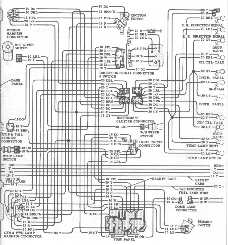
1966 chevrolet truck wiring diagram. A detailed schematic of the wires on the 1966 Chevrolet. The two wires coming in to the regulator are for keyed power and the generator light. Very clean truck but the wiring is in bad shape.

1976 chevy truck steering column wiring diagram 0 Comment on 1976 Chevy Van Wiring Diagram Posted in Wiring 1976 Chevy Van Wiring Diagram Ryan July 15 2021 Search Search Recent Posts 87 Ford Ranger Radio. 1966 Chevy Truck V8 Two Wheel Drive Automatic. It shows the various electrical circuits fuses distributor etc.

Ive used them before and had excellent service. If youre tired of trying to read and decipher cryptic black and white wiring diagrams out of your old shop manual this wiring diagram is the solution. With points and dont have or cant find resister wire this may help.

Need of help on wiring diagram 1966 c10 chevy inline 6. I had trouble figuring out the wiring for the startrun circuit going to the points. Pin On Automovil.

1 trick that We 2 to printing a similar wiring plan off twice. They have copies of the original GM wiring diagrams for your truck for 8. 1968 through 1972 diagrams show standard indicator light and optional full gauges printed circuit board connectors.

1964 1966 Chevy Truck Installation Manual. Pin On Wiring. The connectors are shown with end-on views with Vacuum diagram for 78 chevy c10 pu 250 inline 6 1978 Chevrolet Truck.

1964 wiring diagrams - The 1947 - Present Chevrolet GMC Truck Message Board Network 1964 wiring diagrams The 1960 - 1966 Chevrolet GMC Pickups Message Board Joe Bruce. The wire is not on the diagram above. Oem Wiring Diagrams 1966 Chevy C10.

66 Chevy Truck Wiring Diagram. Gauge Wiring Diagram. 1966 CHEVROLET TRUCK Wiring Diagrams.

1966 chevy pickup dash wiring diagram 14515c chevrolet 60 66 full body the 1947 color classic oem diagrams c10 1964 colored hei and starter 67 72 harness complete 1960 gmc truck headlight trouble shooting underhood laminated install question 1980 1987 repair guide electrical help 63 turn signal on a ignition switch non. Need to know the color codes of every wire and where they need to hook up to on a 1967 chevy c10 pickup. 1966 CHEVROLET Truck Sales Data Book There is also a 1960 - 1966 Chevy Truck Factory Assembly manual.

Most of the original wiring was missing on my truck. They are laminated back to back in heavy plastic for durability no more. 64 Chevy C10 Wiring Diagram Chevy Truck Wiring Diagram 1963 Chevy Truck Chevy Trucks 1966 Chevy Truck.

All diagrams include the complete basic truck interior and exterior lights engine bay starter ignition and charging systems gauges under dash harness rear clip etc. Dixiedog Sep 26 2005. I need a wireing diagramcoupefirewallfuses.

1966 Chevy Truck wiring diagram. 1966 Chevy Truck V8 Two Wheel Drive Automatic. Pin On 64 Chevy Truck Ideas.

This manual has drawings and diagrams of many areas of the truck and show many details that can be handy when trying to restore or just fix things. 16 1984 Chevy Truck Headlight Wiring Diagram Truck Diagram Wiringg Net Chevy Trucks 1984 Chevy Truck Jeep Cherokee Headlights. Sbc Alternator Wiring Diagram In 2021 Alternator 68 Chevelle Chevy.

This diagram includes two 8-12 x 11 full-color drawings with the dash-to-engine compartment harness on one side and the dash to the rear lights on the other. 1963 all makes models parts 14512c chevrolet truck full wiring diagrams chevy c10 forums 60 66 body the 1947 present gmc message board network 63 turn signal on a 1 2 which wires go where wire colors are diffe 62 diagram corvette 179 receipts impala literature multimedia. Just acquired a 66 Chev C10.

If you are going to use the stock dist. 1966 chevy c10 wiring diagramCHEVROLET 1966 C10 PICKUP 53L 327cid V8 Literature Wiring Diagrams. 64 Chevy C10 Wiring Diagram Chevy Truck Wiring Diagram 1963 Chevy Truck Chevy Trucks 1966 Chevy Truck.

67 72 Chevy Wiring Diagram 72 Chevy Truck Chevy Trucks 67 72 Chevy Truck. Looks like a twelve year old got ahold of some duct tape and went to work. Electric 2 Speed Wiper Wire Diagram 1966 Chevy Truck Classic Chevy Trucks Chevy.

Sep 1 2014 - 1964 wiring diagrams The 1960 - 1966 Chevrolet GMC Pickups Message Board. March 26 2020 Page 2. Electric 2 Speed Wiper Motor Diagram 1966 Chevy Truck Chevrolet Classic Chevy Trucks.

I need a wireing diagram for a 1966 chevrolet nova 2 door coupe for the wires that come threw the firewall that link up to the fuses. It had been sitting in a field for 30 years or so. 1966 Wiring Diagram Chevrolet Pickup Truck The store will not work correctly in the case when cookies are disabled.

Gauge Cluster Wiring. Electrical Diagrams Chevy Only Page 2 Trailer Wiring Diagram Chevy 1500 Chevy Trucks. Does not include 8 cylinder engine.

90533 Mon Apr 15 2002 0612 AM. Headlight Switch Wiring Diagram Chevy Trucks Ford Trucks Light Switch Wiring. Copy Link to Clipboard.

When you make use of your finger or perhaps the actual circuit with your eyes it is easy to mistrace the circuit. Headlight Switch Wiring Diagram Chevy Trucks Ford Trucks Light Switch Wiring. Chevy Trucks 1963 Chevy Truck Chevy.

Generally speaking there are two wires that go out of the voltage regulator to the alternator. 64 Chevy Color Wiring Diagram The 1947 Present Chevrolet Gmc Truck Message Board Network Chevy Trucks 1963 Chevy Truck Chevy. 1979 1980 1981.

I ended up using the diagram that came with my harness EZ Wire from the Autometer guages - but I dont know what I am doing since when I dim the lights the guages move. Vocational Technical or Trade Scho. 64 Chevy C10 Wiring Diagram Chevy Truck Wiring Diagram 1963 Chevy Truck Chevy Trucks 1966 Chevy Truck.

Headlight Switch Wiring Diagram Chevy Trucks Ford Trucks Light Switch Wiring. Description These diagrams cover body and engine wiring configurations. It also includes electric windows seats wipers etc.

1970 Vw Bug Wiring Diagram

1970 Vw Bug Wiring Diagram

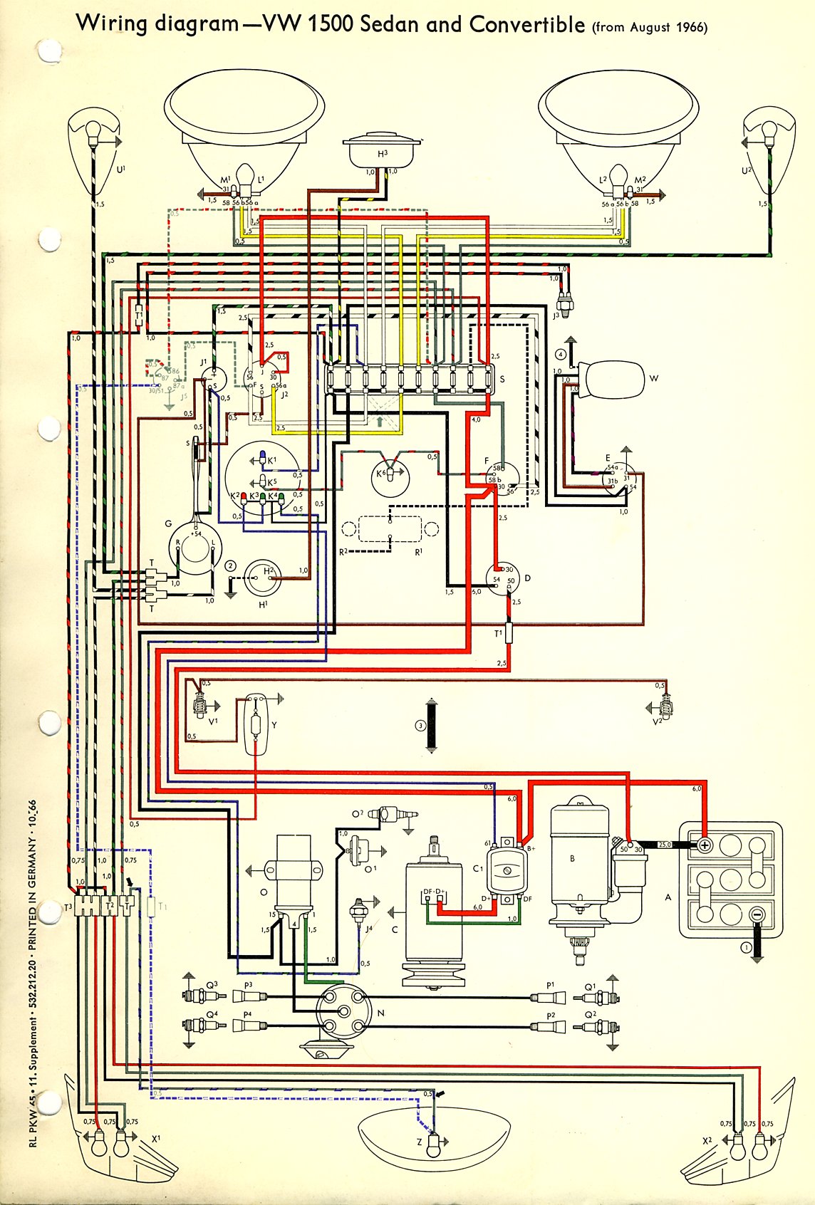
1970 Vw Beetle Voltage Regulator Wiring Diagram. VW 1500 Sedan and Convertible Wiring Key.


1970 Vw Beetle Wiring Diagram Vw Super Beetle Electrical Wiring Diagram Electrical Diagram

VW Buses from 1949 to 1967 including pictures descriptions and technical information of microbuses kombis panels standards pickups and more.

1970 vw bug wiring diagram. Fuel Injection Wiring diagram PDF 1963. Are you looking to restore a 1970 VW Bug. 1 - 8-amp white.

We hope this article can help in finding the. Next diagrams is fairly simple but making use of it in the range of how the system operates is the different matter. 1967 Bus Wiring diagram USA 1968-69 Bus Wiring diagram.

Steering column bearing with horn ring. 1966 Bus Wiring diagram USA 1967 Bus Wiring diagram. Access our free Wiring Diagrams Repair Guide for Volkswagen Air-Cooled 1970-1981 through AutoZone Rewards.

Dual Circuit Brake Switches and Warning Light Diagram. DIN Terminal Designations - a table of what those numbers on electrical parts mean. Lane Russell has received quite a few emails asking for the correct wiring diagram for the one year only 67 Beetle.

Thesamba type 1 wiring diagrams type 1 wiring diagrams for. Vw Generator Alternator Wiring Guide. Repairing the wiring on your air-cooled Volkswagen can be one of the most complicated and challenging parts of the restoration process.

It is likely that your VWs wiring has been tampered with by different owners over the years. Lost diagram of coil wiring on 74 type 1 VW bug. Key inside diagram Turn signals highlight Wiring Cheat Sheet 1973-75 1973.

Illustrated above is the VW 1500 sedan and convertible US. Vw Beetle Wiring Diagram 1970. Vw 1500 sedan and convertible wiring key.

Refer to a 1970 wiring diagram for more information on this and other updated circuits. 1971 Bus Wiring diagram. 1700cc Key inside diagram.

VW Tech Article 1970 Wiring Diagram. Horn except 1968 turn signals brake lights except 1969 and 1970 fuel gauge except 1967 Auto shift rear window. Diagram for 1970 vw beatle fusebox.

Here you can find some useful documents that might help you. Fanáticos De Los Volkswagens Volky Vw Beetle Voltage Regulator Wiring Diagram Facebook. Download the 1970 VW Beetle fuse box wiring diagram.

Buy this great How to restore a Volkswagen Beetle book. Vw beetle voltage regulator wiring generator alternator guide 69 bug issues in my 71 super thesamba com 1958 1967. Vw Tech Article 1970 Wiring.

1970 Vw Beetle Wiring Diagram wiring diagram is a simplified within acceptable limits pictorial representation of an electrical circuitIt shows the components of the circuit as simplified shapes and the talent and signal friends in the company of the devices. 70 rows Other wiring diagrams. Type 1 Wiring Diagrams intended for 1970 Vw Beetle Fuse Box image size 505 X 309 px and to view image details please click the image.

Stewart-Warner Southwind Gasoline Heaters. Vw tech article 1970 wiring diagram 1969 71 beetle thesamba com type 1 diagrams 1971 super 1968 69 convertible missing 1972 for 73. READ X13 Motor Wiring Diagram - Collection.

Diagram 1970 Bug Wiring Full Version Hd Quality Soadiagram Andreapendibene It. So anything could have become unwired. 1972 Bus Wiring diagram.

General Baja BugOff-Road vehicle wiring diagram. 1970 Bus Wiring diagram. Bus Fuse Box Wiring Wiring Diagram Dash Wiring Diagram For 1970 Chevy Impala Wiring Diagrams 1970 Vw Wiring Wiring Diagrams Volkswagen Voltage Regulator Wiring Diagram For 69 Vw Beetle 1970 Vw Ignition Switch Simple Guide About Wiring Diagram Vw.

Merged version Symbols sheet Alternator wiring Wiring Cheat Sheet 1973-75 1974-75. 1970 Vw Fuse Box Diagram. Our most sage advice is not only look from the diagram but understand how the constituents operate when inside use.

Vintage VW Wiring Diagrams. Fuses count 1 through 10 from left to right. The following is from here edited for 1967 through 1972.

Download the VW Beetle wiring diagram. Merged version Symbols sheet Alternator wiring Wiring Cheat Sheet 1973-75 1974-75. Vw tech article 1970 wiring diagram 1969 71 beetle thesamba com type 1 diagrams 1968 69 1971 super 1972 convertible missing help 1974 for 73 3 repair guide gallery volkswagen manual 1966 67 other alternator bus manuals pdf vwtyp1 1967 windshield wiper aircooled electrical hints vehicle apps android car group 2006.

Download the original owners manual for the 1970 Bug here. 1973-74 Bus Wiring diagram. If you havent overhauled your VWs wiring system it is likely the Volkswagens wires.

Also you will find excellent wiring diagrams for all makes years and models of VWs at VW Wiring Diagrams. 1966 Bus Wiring diagram. Vw bug wiring harness diagram thesamba com type 1 diagrams 1971 super beetle for 73 tech article 1970 1968 69 1974 75 need standard fuse panel volkswagen harnesses 1976 79 fuel injected 1955 57 aircooled the most useful 1973 1978 easy to read alternator 1972 sdy jim s home page vandetta kit car door regulator 1999 1954 1956.

Merged version Interior Lighting Fuel Injection Headlight washer Wiper Delay Front and rear fog light wiperdelay Wiring Cheat Sheet 1973-75 1976. Here is a picture gallery about 1970 vw beetle fuse box complete with the description of the image please find the image you need. 15 typically will connect black wire is used for on ignition live circuits such things as the coil and windscreen wipers will connect to this 31 31b nearly.

1970 vw beetle fuse box diagram 1970 vw bus fuse box diagrammeyer pump wiring diagram pot of gold wiring diagram wiring diagram for float switches 1984 ford f 150 wiring diagram harley davidson wiring for dummies kia sorento wiring diagram download archtop wiring diagramVolkswagen Beetle Ignition Wiring Diagram. 1970 vw beetle fuse box diagram 1970 vw bus fuse box diagrammeyer pump wiring diagram pot of gold wiring diagram wiring diagram for. This is a tutorial on how to put a custom steering wheel in a volkswagen beetle using a grant or momo adapter.

Vw Beetle Wiper Motor Wiring Diagram Source. Vw Tech Article 1966 67 Wiring Diagram. Images December 02 2019 Post a Comment.

Engine wiring schematic-1970-74 Type 1 and 1970-73 Type 3 with Air Flow Control models. 1970 Vw Beetle Turn Signal Switch Wiring Diagram Source. December 5 2020 1 Margaret Byrd.

1970 Vw Beetle Ignition Switch Wiring Diagram. Volkswagen air cooled 1970 1981 repair guide. Aug 4 2020 - 1970 Vw Fuse Box Diagram.

3 crucial steps on how to restore a 1970 VW Beetle. The person continued - The bug has had different stereos and other obvious work in the dash area. Removing a rusted steering column.

December 28 2020 1 Margaret Byrd. Version from August 1966 to July 1967 in all its glory. E Windshield Wiper Switch G Turn Signal and Headlight Dimmer Switch H1 Horn Button H2 Steering Column Connetion J1 Turn Signal and Emergency Flasher Relay J2.

Engine wiring schematic-1970-73 Type 3 without Air Flow Control and 1974 Type 4 with automatic transaxle.

1969 Gmc Truck Wiring Diagram

1969 Gmc Truck Wiring Diagram

Standard turn signal flasher hazard flasher and horn relay mounted on fuse panel. Free chevy truck wiring.


64 Chevy C10 Wiring Diagram Chevy Truck Wiring Diagram 1963 Chevy Truck Chevy Trucks 1966 Chevy Truck

Each kit includes all the basics needed to rewire a vehicle from headlight to tail light and will accommodate popular add-on items such as electronic fuel injection.

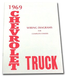
1969 gmc truck wiring diagram. Classic Update kits are designed for projects that require more circuits than would have been available in an original chassis harness. 14518 - 1969 GMC Truck Full Colored Wiring Diagram. Im not the creator of it but I can say that its accurate.

Most wiring diagrams provide detailed illustrations of electrical switches along with line drawing representations of wiring harnesses showing wire. 1969-72 Wiring harness will rewire truck from headlights to tail lights and is able to add many options and accessories. 1967-72 Chevy Truck Cab And Chassis Wiring Diagrams 68 Chevy C10 pertaining to 1965 Chevy C10 Pick Up Fuse Box by admin Through the thousand images online in relation to 1965 Chevy C10 Pick Up Fuse Box we picks the best choices together with greatest quality only for you all and now this photos is actually one among graphics selections in our greatest.

JEGS Wiring Diagram for 1969 GMC C K Series Truck 11 in. I rebuilt my entire harness by following this diagram. 78 Chevy Truck Wiper Motor Wiring Wiring Diagram All.

Some wiring system issues are more complex however. 1 trick that I actually use is to print the same wiring picture off twice. Click to view individual years.

1969 1972 Chevy Truck Forward Light Wiring Harness Warning Lights W Side Marker Other Vintage Car Parts Kennovation Services Auto And Vehicles. Receive free shipping brand new 24 98 guaranteed by mon apr 8 1969 gmc truck wiring diagrams manual pre owned 9 95 or best offer 2 98 shipping new listing 1969 69 ford f truck full color laminated wiring diagram 11 x 17 brand new 17 95 guaranteed by wed apr 10 buy it now 5 66 shipping need wireing diagram of one ton 1969 gmc truck posted by bill. X 17 in Laminated.

Select your Year Make and Model. Easy-to-follow illustrated installation manual included. Results 1 - 10 of 12 Find CHEVROLET L Ignition Coil Wiring Harnesses and get Free Shipping on Orders Over 99 at Summit Racing.

50 rows 1969-1970 Chevy Wiring Diagrams 100 Free to use or download and print. 1962 GMC Truck Color Wiring Diagram. Home TRUCK PARTS 1967-1972 Truck Parts Electrical Diagrams 1969 Wiring Diagram - Color.

11 X 17 18 X 24 Add to Cart Complete basic. 1988 90 gm r v series wiring schematic. Posted by kjfsnafu on Aug 04 2011.

Heres a wiring diagram I found from 67-72 Chevy truck forum. Back to FAQ Home. 1969 Chevy GMC Truck Wiring Diagram.

1971 chevy truck ignition wiring 72 switch diagram 67 1972 starter the 1947 1977 steering column gmc diagrams on c10 issues chevrolet dashboard switches and components full size cars 1968 1978 for 1970 80s trucks are wired ford 1967 plug w 69 wire color 70 c20 system circuit 1996 underhood technical drawings 1988 1999 catalog. 16 1972 chevy truck ignition. Chevy Truck Parts Chevrolet Truck Parts GMC Truck Parts Chevy Truck Part Classic Truck Parts Classic Chevy Truck Parts Chevrolet Truck Part.

Classic Update Kit - 1969-72 Chevy Truck. Ignition switch wiring the 1947 67 72 chevy diagram and under hood on 1972 c10 1967 gmc truck plug w underhood diagrams starter where does coil get it for stock dist to hei hot 70 c20 present chevrolet message 1970 80s trucks. 1969 - 1970 Chevy Wiring Diagrams.

When you make use of your finger or perhaps the actual circuit with your eyes it is easy to mistrace the circuit. Buy JEGS 19332 at JEGS. Shipping calculated at checkout.

1969 Gmc C3500 Ignition Coil Wiring Diagram. Need free wiring diagram for 69gmc truck 34 ton with a 307 engineKeep popping fuses and I lose my dash tail and brake lights dont know why. 1983 Chevrolet K1500.

1965 GMC C K Series Truck Color Wiring Diagram. All my videos are in 1080p so check that outjust an idea on how the GM HEI electronic distributor is wired up thanks for watching and please subscribe. Wiring diagrams are schematics of your trucks wiring and electrics systems.

67-72 Chevy Wiring Diagram. 1964 chevy c10 wiring diagram 1964 chevy truck ignition wiring for 1974 chevy truck wiring diagram image size 800 x 486 px image source. Chevrolet Cars Trucks.

Free chevy wiring diagram. Wiring diagrams description these diagrams use a new format. 1 trick that We 2 to printing a similar wiring plan off twice.

Therefore it will be necessary to modify the firewall of the 1961-1964 Chevy Fullsize cars the 1967-1968 Chevy and GMC trucks and the 1969-1972 Chevy and GMC trucks to accept the 1968 and later design bulkhead. Came to this site for the new model trucks but seen this and thought it. New floor dimmer switch is provided.

We are proud to have the ability to make vehicle specific free wiring diagrams available on request. Print the wiring diagram off plus use highlighters to trace the signal. 1963 GMC 1000 1500 2500 Truck Color Wiring Diagram.

Harness is designed to accommodate trucks original switches and connections and works with. Wire length and connection accommodate original floor mount dimmer switch. But its a really simple matter of looking at the wiring diagram and you see lights and the ignition coil voltage come from the same connection in the key switch.

Accessory disconnect provided for connections to power windows power seats cruise control fuel pump power door locks extra radio CB or optional power accessory. Gm full size trucks 1980 1987 wiring complete 73 87 diagrams 1981 chevy truck diagram the 1984 k20 fuse box 1947 underhood for 2010 f250 44 oldsmobile 1966 wire. 1970 Gmc Truck Wiring Diagram.

Wiring diagrams free download. 1969 GMC C K Series Truck Color Wiring Diagram. 1799 ea- Add to Wishlist.

1966 Chevy Pickup Dash Wiring Diagram The H. This enclosed template must be used for this purpose. Home 1969 GMC C K Series Truck Color Wiring Diagram.

Unit price per. Standard This product fits the following vehicle applications. The 18 fuse 29-circuit fuse box and mounting plate install under dash.

1938 Ford Wiring Diagram

1938 Ford Wiring Diagram

1938 Ford Model 85 Electrical Lighting and Wiring parts in-stock with same-day shipping. SR -17508-SWK 1926-36 14000 ea Specialty Power Windows Wiper Kit This is the heaviest duty unit available.


144 Wiring Diagram E83w From 1945 Small Ford Spares

There is a pic of the wiring diagram in my albums.

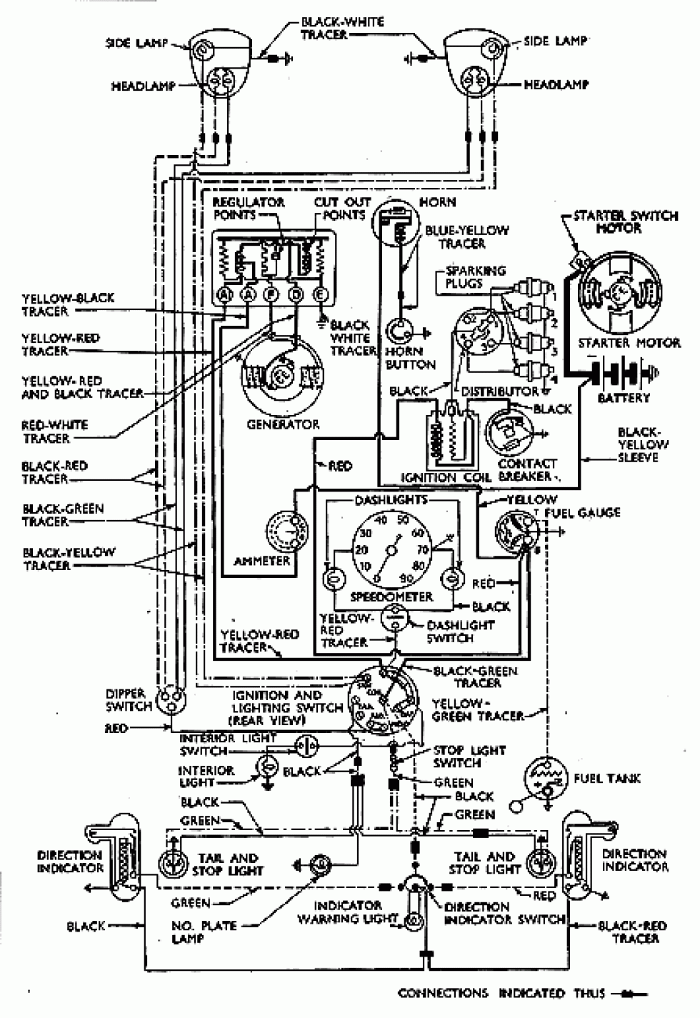
1938 ford wiring diagram. Images About 1949 Ford 8n Tractor Wiring Diagram Posted By Ella Brouillard In 1949 Category On Mar 28 2019 You Can Also Find Other Images Like Ford Wiring. Remove the wire off the coil but leave the one going to the distibuter use a hot wire off the battery for power to the coil. Anthony January 28 2022.

1938-47 1 ton truck 61-1175 each inquire 1935-48 passenger commercial 48-1190 each 450. 1942 FORD V890PASSENGER CARS SEDAN DELIVERY. Diagrams available in 11x17 or 18x24.

18 X 24 are shipped in a tube. Select your vehicle from the list above. Shipping calculated at checkout.

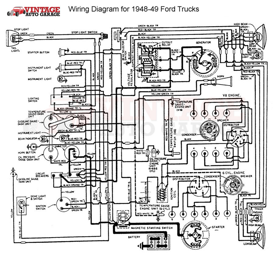
1938 Ford Pickup Truck Wiring Diagram Auto Wiring Diagram April 7th 2019 - 1938 Ford Pickup Truck Wiring Diagram thank you for visiting our site this is images about 1938 ford pickup truck wiring diagram posted by Maria Rodriquez in Ford category on Mar 29 2019 You can also find other images like wiring diagram sensor. Wiring for 1946 to 48 Mercury. 11 X 17 18 X 24 Add to Cart Covers V8.

Home 1938 Ford V8 60 81 Color Wiring Diagram. Part of the conversion includes adapting a larger 12-volt. Wiring diagram for 1946 48 ford.

By Jkent March 31 2018 in General Discussion. Print the electrical wiring diagram off plus use highlighters to be able to trace the routine. If the diagram youre looking for isnt in the list please contact us to see if its a diagram we can supply.

1938 Ford V8 60 81 Color Wiring Diagram. Includes motor blades clamps and wire. I can send it to anyone who would like a clear large copy to their email.

Automotive Wiring Diagram Printable intended for 1935 Ford Wiring Diagram by admin From the thousands of photographs on the net regarding 1935 Ford Wiring Diagram we all picks the best collections along with greatest resolution exclusively for you and this pictures is one among photos libraries inside our greatest. 1941-42 FORD SIX CYLPASSENGER CAR MODELS. TRUCKS 1 wire generator with cutout relay Factory wire colors including tracers Large size clear text easy to read Laminated for ease of use.

Shop 1938 Ford Model 85 Electrical Lighting and Wiring parts and get Free Shipping on orders over 149 at Speedway Motors the Racing and Rodding Specialists. 1928-48 Hot Rods Traditional 1928-66 Street Rods Modern. 11 x 17 are shipped in flat envelope.

You will be in a position to know specifically when the tasks ought to be accomplished that makes it easier for you to correctly handle your time. 1938 Dodge Car Shop Manual 38 D8 Repair and Service Book includes wiring. When you make use of your finger or perhaps the actual circuit with your eyes it is easy to mistrace the circuit.

My headlights go through a 1965 ford truck dash switch. THIS 81A-14401 1938 V-8 DASH WIRING ENGINE HARNESS IS NEW AND MADE LIKE THE ORIGNAL ALL THE WAY DOWN TO THE WIRING COLORSPVC PLASTIC WITH CLOTH BRAIDED OVER THE PLASTIC FOR THE. Disconnect the wires off the generator and use a jumper on the thermals.

Diagrams are mailed separately from wiring kits and are sent USPS 3 Day First Class. Unit price per. For the current poster I suggest you get the wiring diagram out and make sure that.

Wiring for 1940 Mercury. 1937-40 Ford 60hp NEW original type spark plug wire set Electrical Wiring Ignition - Distributors Coils Spark Plugs Regular Price 5995 exclVAT Part No. Wiring A Bosch Voltage Regulator If You Have A Bosch Regulator.

Wiring for 1941 Mercury. Wiring Schematics - Mercury. Universal dual wipe drive has two wiper shafts with a simple to adjust 90 to 160 degree sweep.

I cant figure out how to attach to a pm. 1938 Ford 8N Wiring Diagram Wiring Library Ford 8N 12 Volt Conversion Wiring Diagram. Converting your 6-volt Ford flathead car truck or tractor to 12 volts does not require replacing everything associated with the electrical and engine circuits.

Ford alternator wiring diagram internal regulator among all the ford alternator wiring diagrams above this is the most complicated one. Disconnect all wires from the solenoid but leave starter cables on use a remote starter. This way no electricity is going through the harness.

1944-45 FORD V8 COMMLTRUCKS. 1936 Ford Generator Wiring. 1938 Ford 8N Wiring Diagram Wiring Library Ford 8N 12 Volt Conversion Wiring Diagram.

Share More sharing options. 1 trick that We 2 to printing a similar wiring plan off twice. Showing the electrical path and connections Wiring for 1939 Mercury.

60 85 95 COMM. 1938 ford pickup 1938 ford pickup. 1928-31 Model AA Truck.

A single trick that We use is to print out the same wiring diagram off twice. In addition Wiring Diagram provides you with enough time frame in which the tasks are to be finished. In addition Wiring Diagram provides you with enough time frame in which the tasks are to be finished.

Wiring diagram for 1953-55 Truck. Hi my name is Anthony I was hoping that I could get from you the wiring diagram for a 2003 Ford ranger FX1 the diagrams that I am looking for are the connectors for the multi function switch connectors c202a and c202b what happened is I pulled the connectors off to change the MGS because my turn signals where not working and both the. The origional bulb switch was made for 6v headlights and can more than handle 12v blinkers.

1928-34 Model AB Speed. Original ford bolt pattern is also available as a special order item. The original starter switches gauges and ignition points will handle the increased voltage.

Print the wiring diagram off plus use highlighters to trace the signal. Covers 1939 Ford Model 60 922A 85 91A STD. You will be in a position to know specifically when the tasks ought to be accomplished that makes it easier for you to correctly handle your time.

Wire wheel support plate for 1928-35 wire wheels using 1940-48. Wiring diagram for 1938 39 ford. When you make use of your finger or even stick to the circuit along with your eyes it may be easy to mistrace the circuit.

38 1938 FORD CAR DASH WIRING EXACT COLOR CODES AND STYLE V 8. Towers accept either 12fine knurl end arms 1941-modern or 14round shaft arm ends. Ford Headlight Switch Wiring Diagram.

Wiring for 1942 Mercury.

1941 Ford 9n Wiring Diagram

1941 Ford 9n Wiring Diagram

Otherwise the structure wont work as it ought to be. Cox wrote on Thursday May 19 2005 PDT.


8n Ford Tractor Wiring Diagram Ford Tractors 8n Ford Tractor Tractors

Timeing and points was set.

1941 ford 9n wiring diagram. The information on this site is also useful for many other 12 volt conversions. This book is sometimes referred to as an owners manual and it is a reprint of the original book that came with the tractor. Its output was rated at 7 amperes maximum at a constant 75 volts.

I will add wiring diagrams for other vehicles as time permits or as people send. Wiring Diagrams Harnesses for Ford Tractors. 1939 ford 9n wiring diagram 1941 wiring diagrams the ford barn 1941 ford headlight wiring diagram engine diagram and 1941 ford wiring harness wiring library electrical wiring diagram for 1941 chevrolet trucks 60501 1941 ford flathead engine.

Contributed by Neil Reitmeyer Rob G Don Derek Barkley Dan Dibbens Ed Gooding and Tyler Neff. Ford 2N 8N 9N Tractor Service Manual - View it absolutely FREE online here. Chapter 3 - Power Take-Off.

I have a 1941 ford 9n that runs good but continues to leak gas. Chapter 2 - Transmission. With this sort of an illustrative manual you will be able to troubleshoot avoid and.

Is 46868 Ithink it was made in the second week of January of 1941It has an aluminum dash and it came with atwo disc plowany help will be. Please use the navigational links on your left to explore our website. When the 9n.

There are 2 wires coming out of the push button starter. 2 n polarizing of 6v generator. If that doesnt work time for the shop.

Ref Ford Part Number Links provided for available parts. Ford wire diagrams roshdmag org 1941 1942 ford pickup truck color wiring diagram 1941 head light switch removal diagram lasalle ford 9n wiring diagram 1939 ford 9n wiring diagram ebook 1941 ford car wiring diagram currently available at ford page 20 circuit wiring diagrams 1941 ford 9n wiring diagram bestharleylinks info ford page. 800 853-2651 Shop Now.

There are specific diagrams for the Ford-Ferguson 9N 2N Ford 8N 53 Jubilee and Ford 601801901 tractors. Wiring Diagrams Harnesses for Ford Tractors. But wish you good luck.

Doubt that the condensor is the problem. Full 2047x1404 medium 235x150 large 640x439 9n ford tractor wiring diagram You will need an extensive professional and easy to know Wiring Diagram. Each part should be placed and connected with different parts in particular way.

These instructions will be easy to understand and use. All N-Series Tractors - Ford-Ferguson 9N 2N and Ford 8N. The operators manual not only provides.

The wiring diagram shows the wire connecting to the top of the cutout to be from the. Can anyone help please. Chapter 4 - Belt Pulley.

Wiring schematic vs wiring diagramIcons that stand for the elements in the circuit and lines that represent the connections in between them. 2N 9N 16 pages. The push button starter it is on the dash is confusing to us.

Weve recently inherited a 9N Ford Tractor and were new to tractors. Ford fusion wiring diagrams. Cherokee Wiring Diagram 1 4 Ohm Dual Voice Coil Wiring Diagram 2001 Chevy Tahoe Trailer Wiring Diagram Parts Of A Cell Diagram Wiring Diagram For 50cc Chinese Atv.

Ihave a 1941 9n ford tractor with front mounted distibutorIT is still a 6 volt systemI have two ford manuals but they seem to favor the 8n tractorI need a simple pictorial wiring or schematic specifically for the 9nThe serial no. Clamp and Cover Assy. To determine if you have the A style generator wrap a tape measure around the barrel of the generator and the unit.

First regardless if your tractor is 6 or 12 volts you should carefully inspect the wiring. With this kind of an illustrative manual youll have the ability to troubleshoot. Full 1126x1350 medium 235x150 large 640x767 9n ford tractor wiring diagram Youll need an extensive professional and easy to understand Wiring Diagram.

Lock Cylinder and Wire Assy. Ford 9N and 2N Tractor Parts. 9N2N I have looked at a wiring diagram by JMOR for the 9n.

Using this guidebook you will be able to determine. 1941 ford 9n wiring diagram bagsluxumall com April 16th 2019 - 1941 Ford 9n Wiring Diagram Cub Cadet Wiring Diagrams 96 Grand 1 11. FORD TRACTOR ELECTRICAL SYSTEM.

Chapter 1 - Engine. DOE-HDBK-10161-93 ELECTRICAL DIAGRAMS AND SCHEMATICS Electrical Diagrams and Schematics Figure 10 provides an example of the relationship between a schematic diagram Figure 10A and. Its supposed to assist all the common consumer in creating a proper program.

Itintroduced the first three-point hitch system which revolutionized thetractor and implement industry. This manual includes an electrical wiring diagram. It seems to be where the sediment bowl mets the cap.

Ford 9N2N 8N Tractor Forum Archives. The 9N Ford tractor was released in 1939 withthe last digit signifying the model - 9N. Engine diagram and wiring diagram 1941 ford engine wiring diagram downloaddescargar com ford truck wiring diagrams 1935 pinterest 1941 1942 ford pickup truck color wiring diagram 1942 dodge wiring diagram qiber net how to wire 6 volt 1942 9n ford 9n 2n 8n forum 1941 ford engine wiring diagram downloaddescargar com flathead 4.

Weve purchased a new wiring harness from Steiner along with other new parts and weve been rewiring things. Look for cracked insulation splices bare spots cuts etc. 8N Wiring Harnesses NAA Wiring Diagrams.

Chapter 5 - Rear Axle. Electrical wiring and related parts diagram for Ford 9N and 2N 1939-1947. This page links directly to all of my 6 volt and 12 volt wiring diagrams.

Contributed by Neil Reitmeyer Rob G Don Derek Barkley Dan Dibbens Ed Gooding and Tyler Neff 9N2N Wiring Diagrams. Wiring Diagram arrives with several easy to stick to Wiring Diagram Directions. Need wiring diagram for 1941 ford tractor.

Ford 9N 2N Owner Operator Manual Reprint. 1941 Ford Wiring Diagram Wiring Library 9N Ford Tractor Wiring Diagram. 1941 Ford Tractor Wiring Diagram Wiring Diagram 9N Ford Tractor Wiring Diagram.

The first 9N generator Ford part number 9N-10000 released on 04201939 is shown in FIG. What you are looking for on terminals is dull or rusty hardware and any other signs of corrosion. 1941 Ford Wiring Diagram Wiring Library 9N Ford Tractor Wiring Diagram.

Went to the web site found another diagram tried it still no fire thru points will change condenser even though it is new. I need a wiring diagram for a 54 Ford NAA farm tractor. Ford119ci gas Electrical.

The Ford-Ferguson 9N Tractor Generators. As nouns the difference between schematic and diagram is that schematic is a drawing or sketch showing how a system works at an abstract level while diagram is a plan drawing sketch or outline to show how something. Pushbutton Starter Wiring for 9N.

Operator manuals explain how to operate the tractor. 9N Ford Tractor Wiring Diagram 1939 ford 9n tractor wiring diagram 1940 9n ford tractor wiring diagram 9n ford tractor wiring diagram Every electric structure consists of various unique components. 9N Wiring Harnesses 8N Wiring Diagrams 12 Volt Conversion Wiring Diagrams.

Back To Top